Behandelingsoplossingen voor de fijne chemische industrie
The RP Techniek BV Regenerative Thermal Oxidizer (RTO) is widely used across industries such as pharmaceuticals, dyes, pesticides, chemical intermediates, and new energy batteries, effectively treating process waste gases generated during production.
- Characteristics of waste gas: the waste gas contains nitrogen-containing organic matter, sulfur and chlorine organic pollutants and inorganic acid-base waste gas
- Source of waste gas: workshop production process tail gas and waste gas collected by sewage treatment plant
- Waste gas components: ammonia, esters, hydrocarbons, benzene series, hydrogen chloride, hydrogen sulfide
- Process scheme: pretreatment + RTO + SCR + desulfurization chlorine
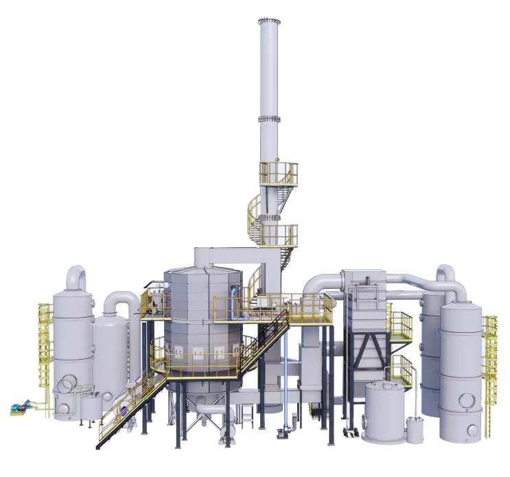
Processchema
To effectively manage and treat waste gas, a multi-stage treatment process is proposed. This integrated approach consists of:
- Pretreatment: This stage removes large particulates and adjusts the temperature and humidity of the gas stream, preparing it for subsequent treatment stages.
- Regenerative Thermal Oxidizer (RTO): Here, the waste gas is heated to high temperatures, oxidizing organic compounds into carbon dioxide and water vapor.
- Selective Catalytic Reduction (SCR): Following the RTO, SCR reduces nitrogen oxides (NOx) by using a catalyst and a reducing agent such as ammonia, converting them into nitrogen and water.
- Desulfurization and Dechlorination: The final steps focus on removing sulfur and chlorine compounds. Desulfurization converts sulfur dioxide (SO₂) into harmless byproducts, while dechlorination treats compounds such as hydrogen chloride, ensuring the emitted gas meets strict environmental standards.
By implementing this multi-stage process, the RP Techniek BV RTO system delivers a reliable and efficient solution for waste gas treatment in the fine chemical industry, enhancing environmental protection and supporting sustainable industrial practices.
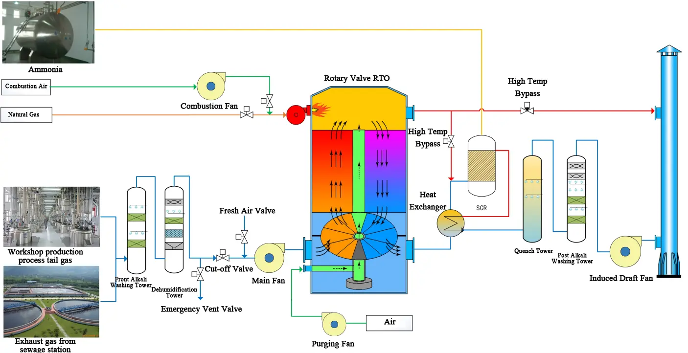
VOCs treatment process in fine chemical industry
Key Safety Technologies
Safety is the fundamental priority in the design and operation of our RTO systems. The integrated control program features self-diagnostics and multi-level safety interlocking to ensure operational reliability. Critical safety components—including flame arrestors, rupture disks, and emergency venting—are installed to prevent hazardous incidents. Functions such as differential pressure detection, combustion system safety control, and high-temperature bypass valves further enhance system protection. At our company, safety is not just a feature—it is our lifeline, embedded in every design and process. The specific measures are as follows:
Pre-treatment System Integration Technology
Exhaust gases must undergo a series of physical or chemical pretreatment processes to meet the inlet requirements before entering a Regenerative Thermal Oxidizer (RTO). Not all exhaust streams are suitable for RTO treatment: the organic concentration should remain below 25% of the lower explosion limit, and substances prone to reaction or polymerization—such as styrene—should be avoided to prevent fouling and safety risks. Additionally, particulate levels must be kept under 5 mg/m³, especially when sticky contaminants like tar or paint mist are present. The gas stream should also exhibit stable flow, temperature, pressure, and concentration without significant fluctuations to ensure continuous and safe operation. Adherence to these guidelines is essential to maintain high treatment efficiency and avoid operational hazards.
1. Exhaust gas concentration exceeds the lower explosion limit (LEL) and the high-concentration exhaust gas is gaseous at room temperature
Compress the exhaust gas using a compressor and then deliver it to the RTO for treatment in a measured quantity.
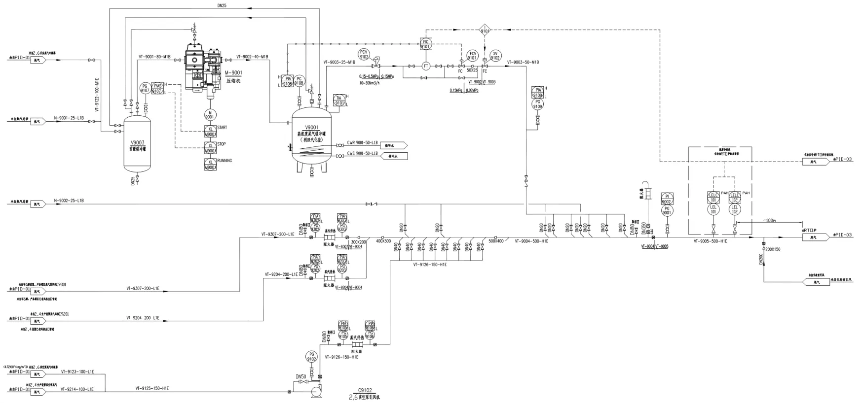
2. Exhaust gas concentration exceeds the LEL and the high-concentration exhaust gas is liquid at room temperature
Control the outlet exhaust gas concentration by condensing it in a condenser based on the properties of the VOCs in the components. Select a solvent with a high solubility for the high-concentration exhaust gas to absorb it.
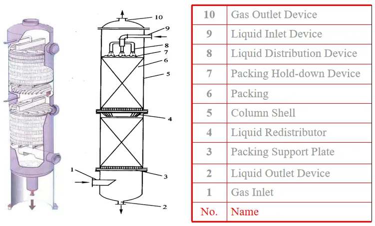
3. Exhaust gas concentration exceeds the LEL
To manage streams with concentrations exceeding the LEL, oxygen content should first be reduced using inert gases like nitrogen or CO₂ to bring concentrations below LEL, followed by further dilution with air to under 25% of LEL. Ignition sources must be controlled; when using air dilution, water spray can be applied to eliminate potential sources, with spray water replacement frequency based on VOC solubility. Storage and controlled release via large atmospheric tanks or pressurized vessels is also an effective method.
4. Exhaust gas contains inorganic acids, alkalis, and salts
Acid washing is used to remove alkaline components, alkali washing is applied to neutralize acidic contaminants, and water washing can eliminate inorganic salts from the exhaust stream.
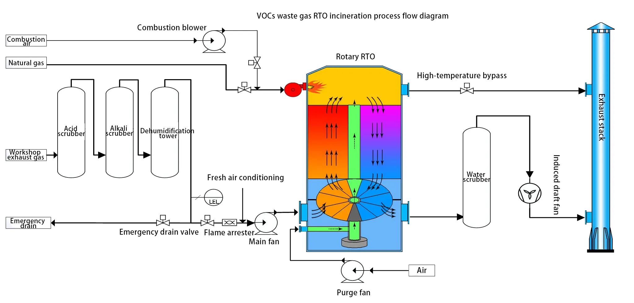
5. High water vapor content, gas condensation
For gases with high water vapor content, dehumidification equipment should be installed. Pipelines should be sloped to facilitate drainage considering the effect of temperature on saturated vapor pressure. Drain outlets should be installed at low points of fans, equipment, and stacks without compromising system negative pressure.
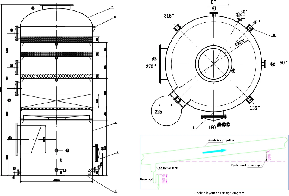
6. Control the concentrations of low-ignition-point exhaust gases, ammonia, and chlorine-containing organic compounds
Concentrations of low flash-point substances should be controlled to prevent combustion at the bottom of the regenerative bed. Chlorinated organic compounds should be reduced to minimize hydrochloric acid corrosion, using adsorption or absorption when necessary. When treating chlorine-containing waste gases, ammonia levels must be managed via water or acid washing to prevent ammonium salt deposition and clogging in the ceramic media.

7. Viscous Matter and High-Boiling-Point Substances
The pretreatment strategy combines mechanical filtration with automated steam backwashing to intercept and remove contaminants, while temperature conditioning is applied to reduce the content of viscous components and high-boiling-point substances in the exhaust gas.
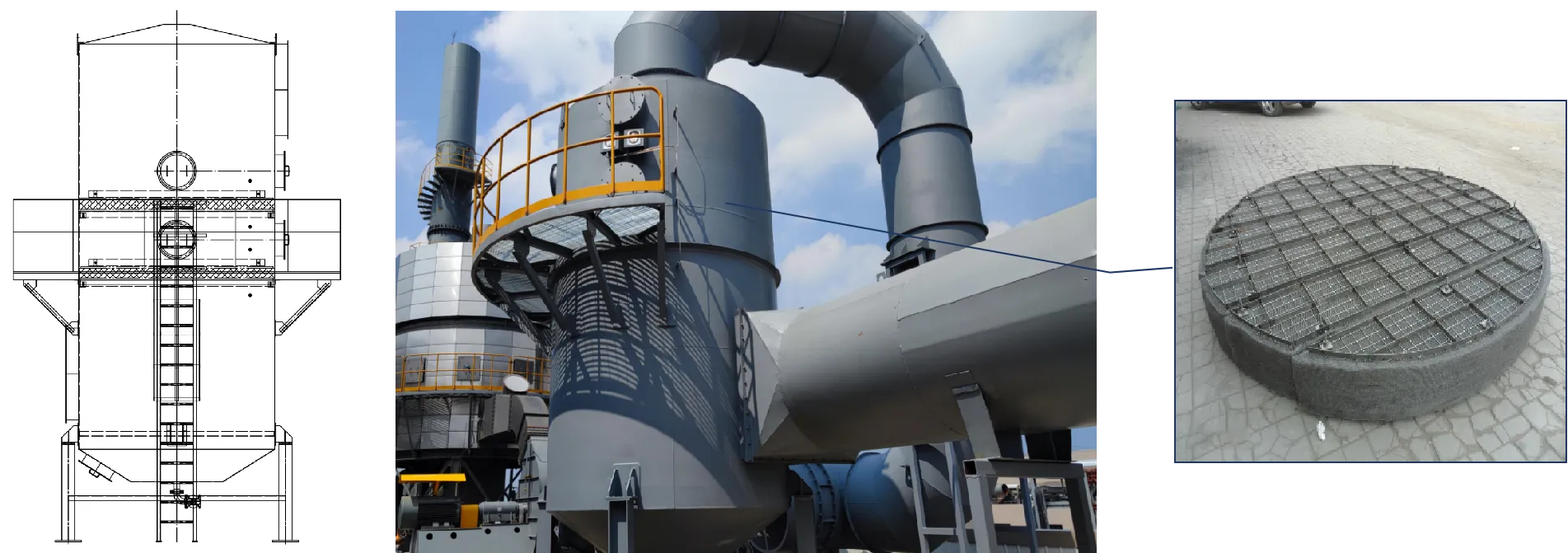
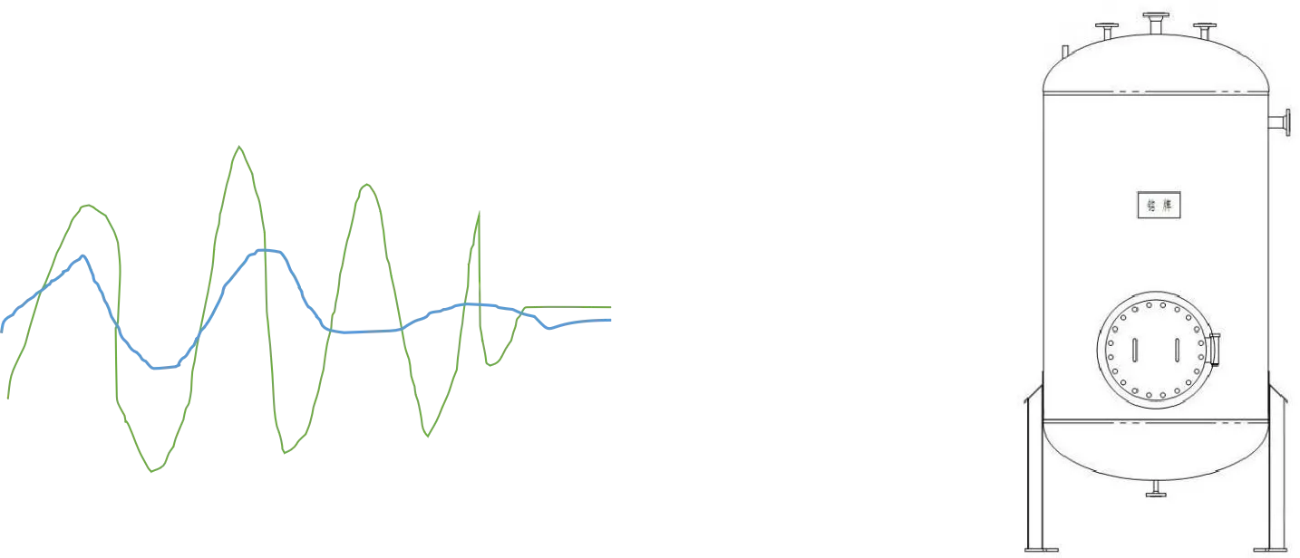
8. Concentration Fluctuation Buffer
Buffer tanks can also function as liquid seal vessels, providing mixing and homogenization of the gas stream while dampening concentration variations.
Post-treatment System Integration Technology
The RTO post-treatment system refers to the process in which the exhaust gas, after undergoing RTO thermal oxidation treatment, undergoes a series of physical or chemical treatment methods to ensure that the gas exiting the RTO meets emission standards. The purpose of post-treatment is to ensure that all emission indicators meet emission standards.
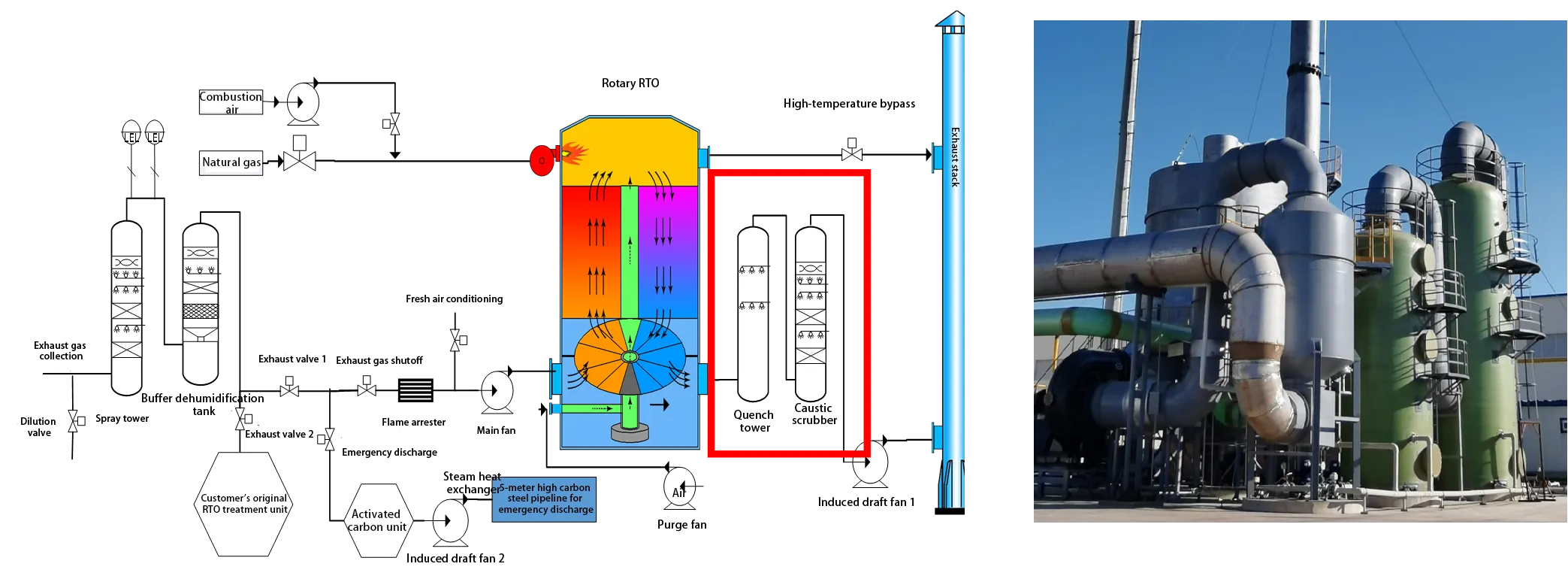
1. Alkali Scrubbing Unit
Adsorption of SO₂, HCl, COCl₂.
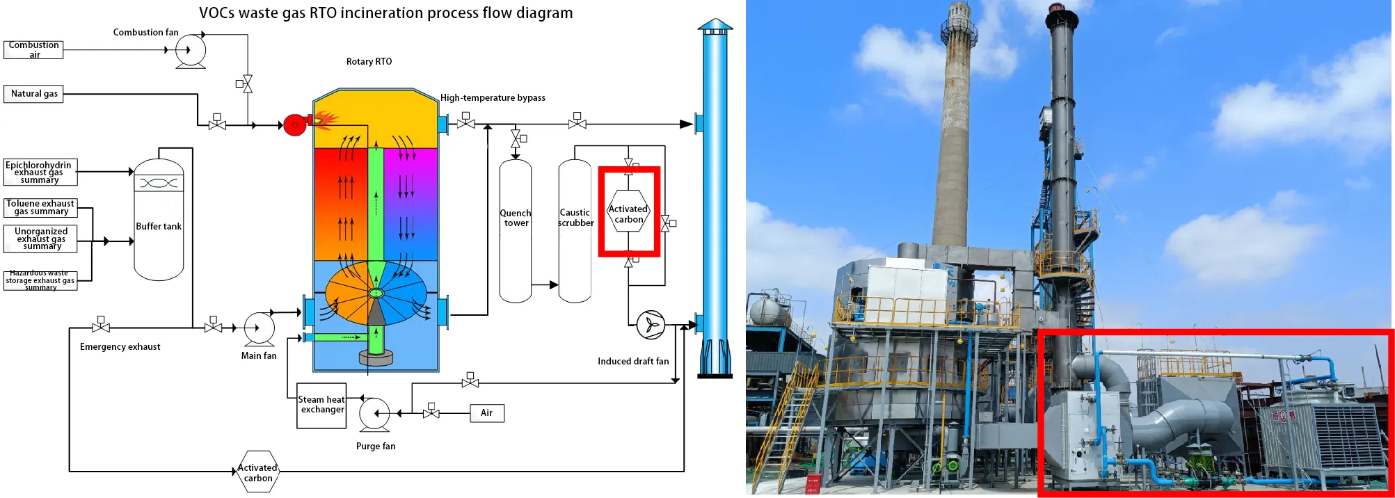
2. Activated Carbon Adsorption Unit
Adsorption of Dioxins and other substances with special emission requirements.
3. Denitrification Unit
SNCR Denitrification: Efficiency <60%. SNCR, without the use of a catalyst, uniformly injects an amino-based reducing agent, such as ammonia or urea, into the flue gas at temperatures between 850°C and 1100°C. The reducing agent rapidly decomposes within the furnace, reacting with NOx in the flue gas to produce N2 and H2O (with little reaction to oxygen in the flue gas), thereby achieving denitrification.
SCR denitrification: Highly efficient. SCR is the most widely used flue gas denitrification technology internationally. It is used in most power plants in countries and regions such as Japan, Europe, and the United States. It produces no byproducts, does not cause secondary pollution, has a simple device structure, and offers high removal efficiencies (over 90%), reliable operation, and easy maintenance. The SCR technology works by injecting ammonia into flue gas at a temperature of approximately 180-420°C over a catalyst, reducing NOₓ to N₂ and H₂O.
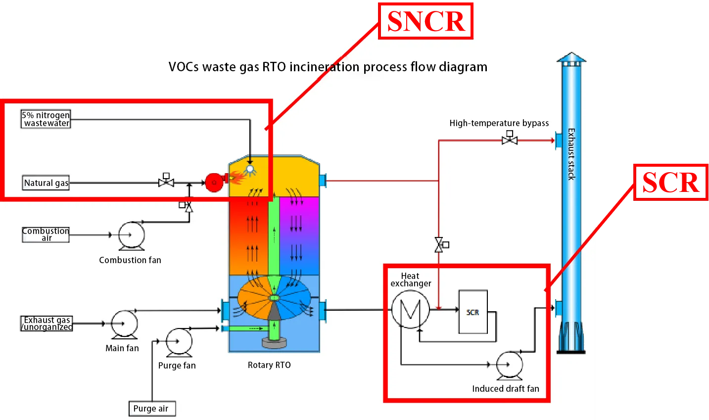
Rotary RTO+SNCR denitrification+SCR denitrification=emissions meeting standards
The solution adopts internationally advanced rotary RTO technology, ensuring high purification efficiency and thermal efficiency. Wastewater containing 5% ammonia is directly sprayed into the RTO combustion chamber via atomizing guns, with temperature controlled at 850–950°C, creating SNCR high-temperature denitrification conditions achieving 30–50% NOx removal. This approach simultaneously treats ammonia-containing wastewater and performs denitrification, realizing a “waste-treats-waste” and “dual gas-liquid treatment” strategy while reducing the load on downstream SCR. For residual NOx emissions from the RTO, an advanced SCR system is integrated, forming a combined SNCR-SCR denitrification process that operates with low energy consumption and high efficiency.
Ammonium Salt Crystallization Control Treatment Technology
1. Prevention of Ammonium Salt Formation
A. Categorized Collection and Treatment
- Waste gas containing ammonia is collected and treated separately, not mixed with chlorine- or sulfur-containing waste gas.
- Waste gas containing chlorine is collected and treated separately, not mixed with ammonia-containing waste gas.
- Waste gas containing sulfur is collected and treated separately, not mixed with ammonia-containing waste gas.
B. Pretreatment Measures for Source Reduction
- For waste gas containing trace ammonia along with chlorine, sulfur, or nitrogen organics, use front-end acid washing + alkali washing + dehumidification to remove ammonia-containing components and reduce ammonium salt formation.
- For waste gas containing both ammonia and trace HCl/SO₂, apply front-end alkali washing + dehumidification to remove acidic components and minimize ammonium salt generation.
2. Mitigation of Ammonium Salt Formation
To reduce ammonium salt formation, front-end pipelines can be heated via preheating, trace heating, hot air purging, and insulation to elevate the temperature considering the decomposition temperature of ammonium salts.
3. Mitigation of Ammonium Salt Clogging
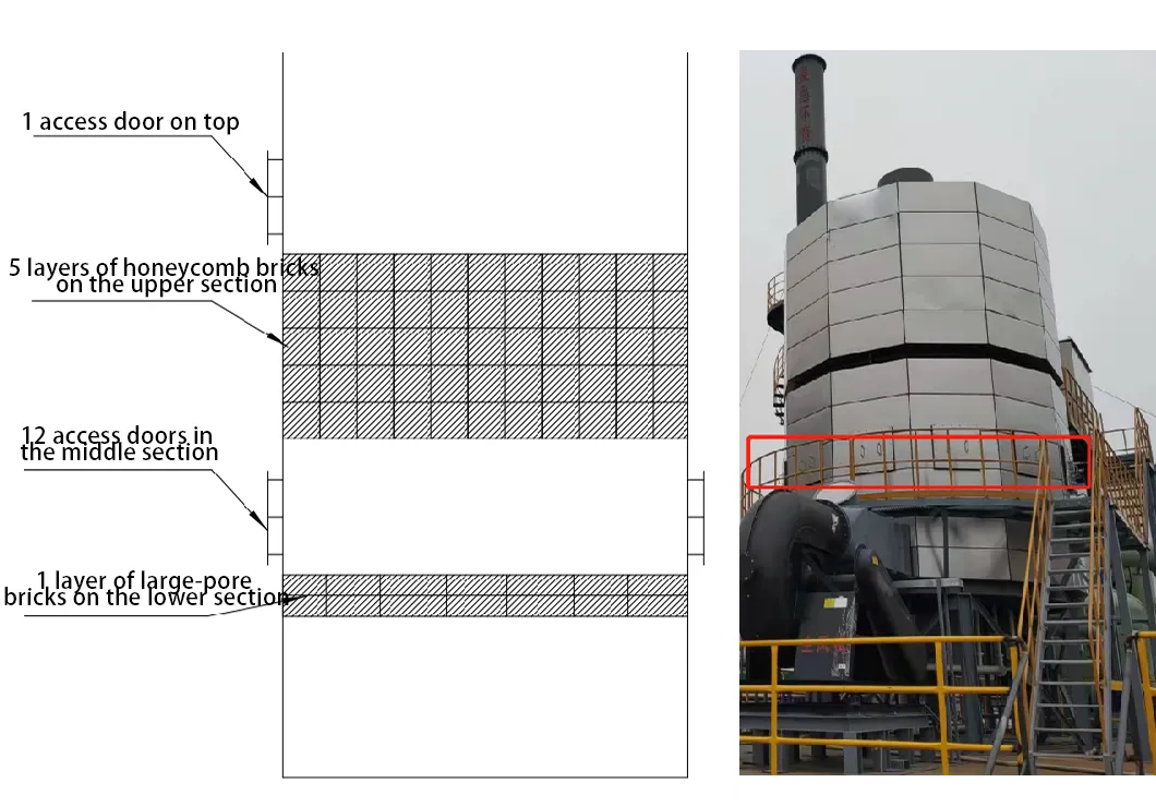
Use clog-resistant regenerative ceramics: the upper five layers of the regenerative chamber employ honeycomb ceramics, while the bottom layer uses large-aperture ceramic media. This combination ensures excellent heat storage performance while reducing the risk of clogging.
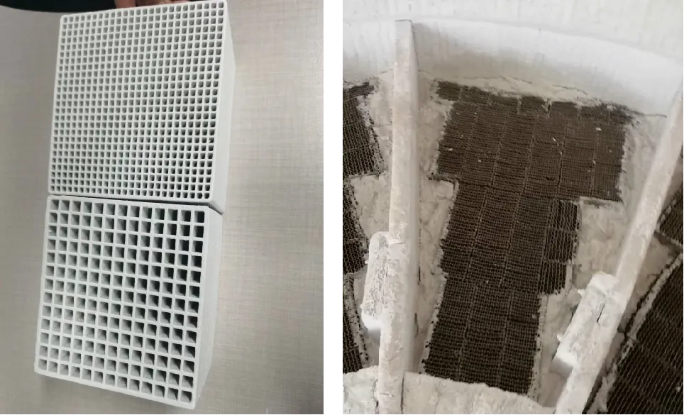
4. RTO Ammonium Salt Cleaning Design
A. Quick-Disassembly Access Door Design
B. Complete Liquid Drainage Structure of the RTO Furnace
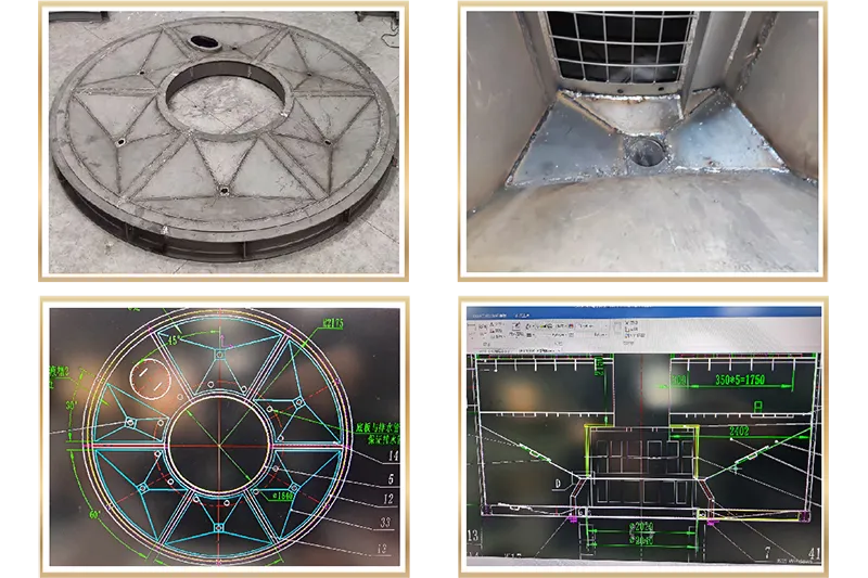
C. Bottom Drainage Design of the RTO
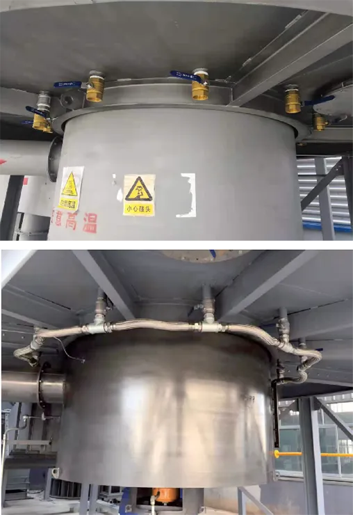
Anti-corrosion Technology
In recent years, regenerative thermal oxidation (RTO) incinerators have gained widespread recognition and application as one of the most effective methods for treating organic waste gas. This has also exposed many pressing challenges and challenges that require innovation: balancing the investment and operating costs of RTO equipment with the selection of corrosion-resistant structural materials and corrosion tolerance.
After years of hard work and extensive experimentation, RP Techniek BV has developed a comprehensive anti-corrosion solution. This encompasses waste gas source-to-process control, including controlling chlorine and water content; preheating the inlet air; heating the purge air; operating the rotating motor at reduced frequency; and reducing the number of regenerative bricks. Details are shown in the diagram to the right.
Low Nitrogen Technology
SNCR
SNCR denitrification offers multiple advantages: it is a clean technology without generating solid or liquid pollutants or by-products, thus avoiding secondary pollution; it demonstrates good economic performance due to the absence of expensive catalysts, resulting in lower investment and operating costs; and the system is simple—mainly consisting of a reductant storage and injection system, including tanks, pumps, injection lances, and necessary piping and instrumentation. Thanks to its simple equipment requirements, SNCR can be installed during a routine maintenance period with a short shutdown duration of approximately 15 days, minimizing impact on operations.
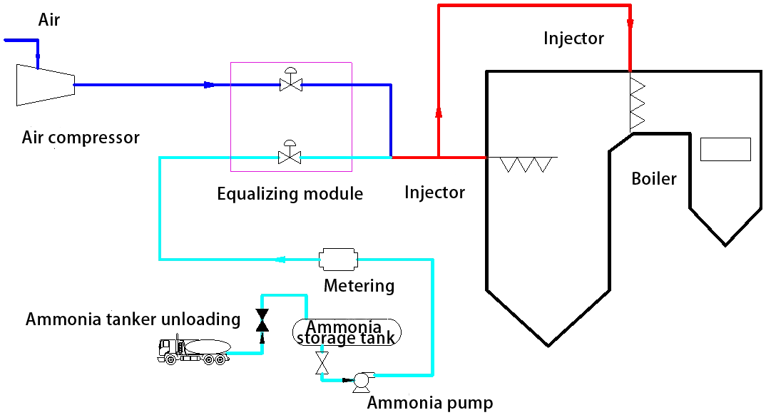
SNCR Denitrification Process Schematic Diagram
SCR
The SCR system includes the flue, SCR reactor, catalyst, ammonia injection system, denitrification agent storage and supply system, maintenance instrumentation and control system, and electrical system. The catalysts used in SCR are mostly based on TiO2, with V2O5, V2O5-WO3, or V2O5-MoO3 as the active ingredients. They are manufactured in three types: honeycomb, plate, or corrugated. SCR catalysts used in flue gas denitrification can be categorized as high-temperature catalysts (345°C to 590°C), medium-temperature catalysts (260°C to 380°C), and low-temperature catalysts (80°C to 300°C). Different catalysts have different optimal reaction temperatures.
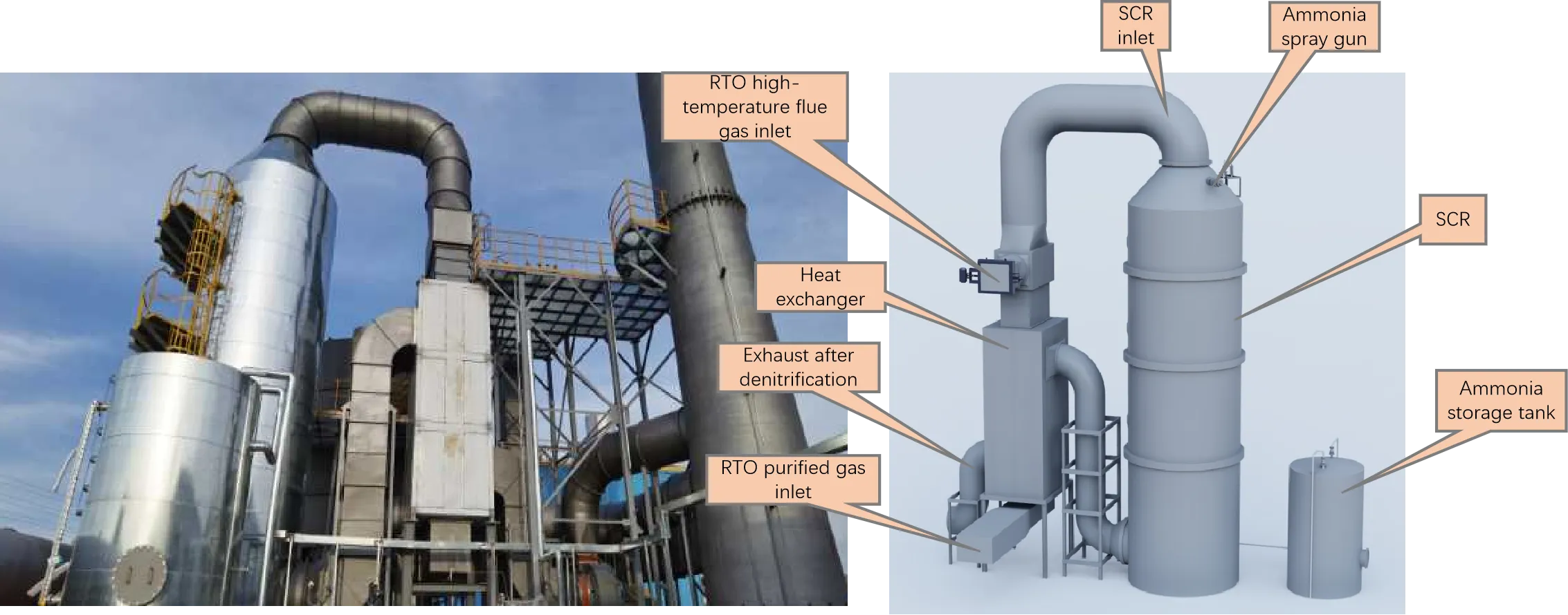
SCR Denitrification Unit Diagram
RTO+SNCR Operation Interface
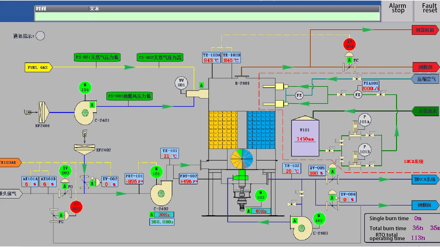
RTO+SCR Operation Interface
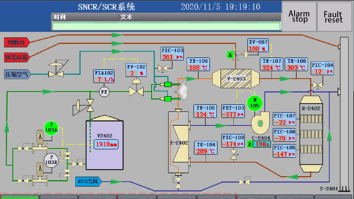
Ammonia injection system optimization
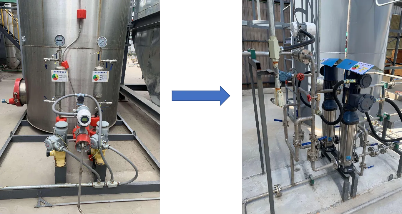
A back-pressure valve is used to regulate the outlet pressure of the ammonia pump. Once pressure is adjusted, no modifications are required, allowing for a more streamlined skid installation.
