مطالعه موردی · کنترل انتشار گازهای صنعتی
How a leading lithium carbonate producer achieved simultaneous ultra-low emission compliance for SO₂, NOx, PM, tellurium, fluoride, and acid mist from 100,000 Nm³/h of tunnel kiln off-gas — deploying a pioneering five-stage integrated treatment system combining filling tower scrubbing, COA oxidative denitrification, limestone-gypsum FGD, wet electrostatic precipitation, and magnetic plume abatement.
COA Oxidative Denitrification
رسوبگر الکترواستاتیک مرطوب
Tellurium & Fluoride Recovery
White Plume Abatement
۰۱ — پیشینه صنعت
Lithium Carbonate as a Critical Battery Material and the Tightening Emission Regulatory Environment
Lithium carbonate is an essential raw material in the production of lithium-ion battery cathode materials, glass ceramics, and specialty chemicals. The explosive global growth of electric vehicles and grid-scale energy storage systems has driven rapid expansion in lithium carbonate production capacity, with output growing from 4.1 t/a in 2014 to 39.5 million tonnes in 2022 — a 28% compound annual growth rate — and projected to reach 110 million tonnes per year with further growth to 51.79 million tonnes projected at 31.1% annual growth. Lithium carbonate production is central to the new energy vehicle supply chain, with national policy in multiple jurisdictions designating new energy, new materials, and new energy vehicles as five-year plan strategic development priorities.
The producer in this case study specializes in new energy lithium materials and rubidium-caesium technology R&D, production, and sales. A significant integrated enterprise built around rich local lithium and rubidium cloud mica resources, it has developed advanced cloud mica lithium extraction technology that addresses the traditional high energy consumption and low recovery challenges of the extraction industry. The enterprise is backed by a parent company with advanced technology resources and participates in the lithium material and battery system value chain as a vertically integrated supplier.
The battery-grade lithium carbonate production process uses tunnel kilns for high-temperature sintering of carbonate precursors. These tunnel kilns, fired on natural gas, generate 100,000 Nm³/h of flue gas at 220°C carrying a complex mixture of SO₂, NOx, fine particulates, tellurium compounds, fluorine compounds, and nitrogen oxide species from both the high-temperature combustion chemistry and the evaporation of trace contaminants from the carbonate raw materials. As environmental regulations have tightened — particularly following the 2024 Pollution Discharge Permit Management Regulations and EU-aligned emission control policy — the requirement for lithium carbonate tunnel kiln off-gas to achieve ultra-low emission compliance has become unavoidable.
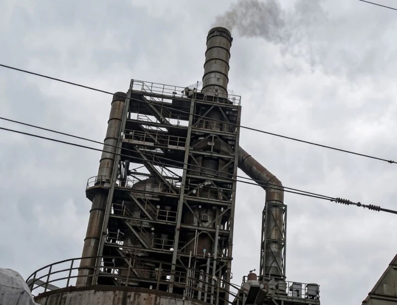
“Lithium battery carbonate tunnel kiln off-gas presents a unique multi-pollutant control challenge: the simultaneous presence of SO₂, NOx, tellurium compounds, fluoride, and fine particulate matter, combined with a white plume from high-humidity post-scrubber exhaust, requires five distinct treatment technologies operating in coordinated sequence. No single technology can address all these pollutant categories.”
— Engineering Technical Summary, New Energy Lithium Battery Industry Flue Gas Purification Project
۰۲ — مشخصات آلودگی
Tunnel Kiln Off-Gas: Seven Simultaneous Pollutant Categories Including Tellurium and Fluoride Recovery
The lithium battery carbonate tunnel kiln is fired by natural gas with a consumption rate of approximately 1,000 m³/h. The kiln generates 100,000 Nm³/h (180,000 Nm³/h at process conditions) of off-gas at 220°C. The off-gas carries the following regulated pollutant categories simultaneously:
- SO₂ at 100–500 mg/Nm³ initial concentration (range reflects batch-to-batch carbonate raw material variability). Target outlet: ≤80 mg/Nm³ via limestone-gypsum FGD with 84% removal efficiency. The wide inlet range means the FGD system must be sized for the maximum 500 mg/Nm³ scenario.
- NOx at 30–50 mg/Nm³. Unlike industrial boiler or smelting furnace NOx at much higher concentrations, the tunnel kiln NOx is at relatively moderate levels but still must meet the ≤80 mg/Nm³ limit. COA (Chlorine Dioxide Oxidation or Catalytic Oxidation Absorption) denitrification achieves 60% removal efficiency at this concentration range.
- Particulate matter (PM) at 30–50 mg/Nm³. Target outlet: ≤20 mg/Nm³. Fine carbonate and oxide particulates from the sintering process. Wet electrostatic precipitator achieves 60% dust removal alongside the other PM polishing effects of the scrubbing stages. Actual dust removal efficiency across the complete system: approximately 69%.
- Tellurium (Te) compounds at 0.5–10 mg/Nm³. Target outlet: ≤0.05 mg/Nm³. Tellurium is a strategically critical rare element present as a trace impurity in some lithium carbonate raw materials, which evaporates during high-temperature sintering and must be both captured for recovery value and controlled to the extremely low emission limit. The filling tower (packing tower) scrubber stage achieves 99.5% tellurium removal efficiency, recovering the tellurium for reuse.
- Fluoride (HF) at 0.16–20 mg/Nm³. Target outlet: ≤6 mg/Nm³. The wide inlet range reflects variability in raw material fluoride content. Limestone scrubbing forms insoluble calcium fluoride during FGD, contributing to fluoride removal alongside the acid gas scrubbing stages.
- Acid mist (fog) at 23–30 mg/Nm³. Target outlet: ≤15 mg/Nm³. Fine acid aerosol droplets from the scrubbing stages must be captured before final discharge. The wet electrostatic precipitator provides acid mist removal alongside fine particle polishing. Acid mist removal efficiency: 70%.
- White visible plume. The post-scrubber exhaust is saturated with water vapor and residual aerosol at approximately 40°C. A Magnetic Plume Abatement (MPA) wet electrostatic precipitator combination provides the final polishing to achieve invisible discharge under all ambient conditions.
| پارامتر | غلظت اولیه | پریز (طراحی) | EU IED / NER Limit |
|---|---|---|---|
| اکسیدهای نیتروژن | 30–50 mg/Nm³ | ≤80 mg/Nm³ | IED 2010/75/EU: 100 mg/Nm³ (combustion) |
| SO₂ | 100–500 mg/Nm³ | ≤80 mg/Nm³ | Dutch Activities Decree NER |
| ذرات معلق (PM) | 30–50 mg/Nm³ | ≤20 میلیگرم بر نیوتن متر مکعب | Dutch Activities Decree NER ≤5 mg/Nm³ |
| Tellurium (Te) | 0.5–10 mg/Nm³ | ≤0.05 mg/Nm³ | IED BAT heavy metals |
| Fluoride (HF) | 0.16–20 mg/Nm³ | ≤6 mg/Nm³ | IED 2010/75/EU HF BAT |
| Acid mist (fog) | 23–30 mg/Nm³ | ≤15 mg/Nm³ | IED BAT |
| ستون سفید قابل مشاهده | Present | هیچکدام (نامرئی) | هیچ ستون سفید قابل مشاهده ای وجود ندارد |
| Rated (standard) flue gas volume | 100,000 Nm³/h | — | — |
| Process flue gas volume | 180,000 Nm³/h (at conditions) | — | — |
| دمای گاز دودکش (خروجی کوره) | 220°C | — | — |
03 — Treatment Solution
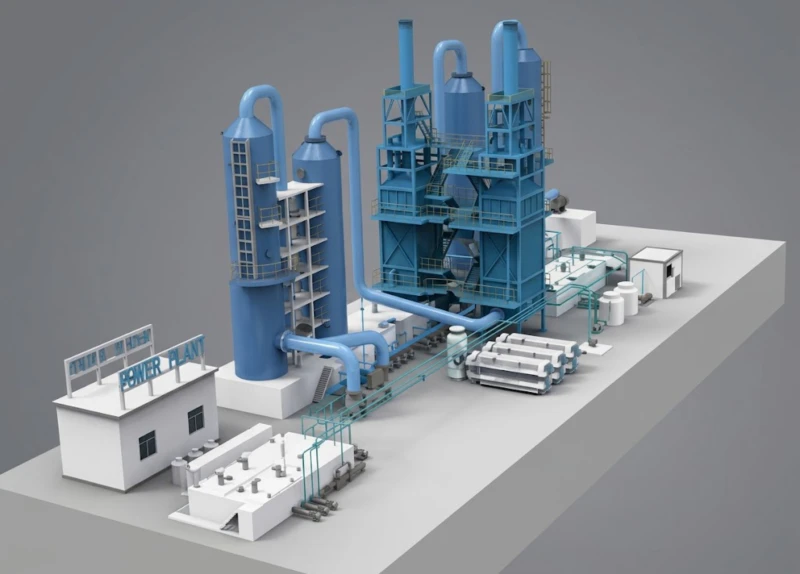
Five-Stage Integrated Purification System with Tellurium Recovery and White Plume Elimination
The integrated treatment system was designed to address all seven pollutant categories in a coordinated five-stage sequence. Rather than treating each pollutant in isolation, the system exploits the cross-capture benefits of each stage and coordinates the reagent chemistry so that one stage’s reaction by-products support the next stage’s efficiency.
Stage 1: Pre-cooling at Induced Draft Fan Inlet
A cooling water additive is applied at the induced draft fan inlet to lower the flue gas temperature from 220°C to approximately 120°C, preventing anti-corrosion materials from exceeding their rated temperature throughout the downstream treatment equipment, and protecting the wet scrubber internals from thermal damage.
Stage 2: First-Stage Filling Tower (Packing Tower — Tellurium & Fluoride Removal)
Gas at approximately 120°C enters the first-stage filling tower where it contacts recirculating scrubbing liquor. In this tower, tellurium compounds and fluoride in the gas react with water to form soluble compounds that are absorbed into the scrubbing liquid. As the filling tower circulating liquid level gradually rises, part of the tellurium and fluoride-containing waste water is transferred to the thickening/desalting adjustment tank by transfer pumps. This primary tellurium-containing wastewater, combined with added calcium fluoride, undergoes a reaction: calcium fluoride addition causes calcium fluoride precipitation, and the liquid is further processed by pressure filtration to achieve solid-liquid separation, removing water-soluble fluoride and achieving water recycling. The key to this stage is pH control in the filling tower (tellurium removal tower) recirculating liquid, simultaneous adjustment of the circulating pump operation based on flue gas temperature and tellurium compound content, and regulation of the tellurium addition and promoter addition quantities. The filling tower achieves 99.5% tellurium removal and 70% fluoride removal efficiency.
Stage 3: COA Denitrification System
The post-scrubber gas re-enters the COA (Chlorine Dioxide Oxidation / Catalytic Oxidative Absorption) denitrification system. At this point, the flue gas still contains oxidizable NOx. The COA denitrification mechanism oxidizes NO (poorly water-soluble) to NO₂ (highly water-soluble) using a chlorine dioxide oxidant, enabling subsequent wet scrubbing absorption to achieve significant NOx removal that conventional water or alkaline scrubbing alone cannot achieve. The COA system achieves 60% denitrification efficiency, reducing NOx from 30–50 mg/Nm³ inlet to ≤80 mg/Nm³ outlet. After COA denitrification, the gas then proceeds to the FGD stage for sulfur dioxide removal.
Stage 4: Limestone-Gypsum FGD Tower (φ4.6 m, 202,000 Nm³/h)
The post-COA gas enters the limestone-gypsum FGD tower for SO₂ removal. The FGD tower achieves 84% desulfurization efficiency, reducing SO₂ from 100–500 mg/Nm³ to ≤80 mg/Nm³. Key parameters: tower internal diameter φ4.6 m; liquid-to-gas ratio 15.5; spray layers 3; single pump flow 600 m³/h; slurry settling time 5 h; limestone operating consumption 65 kg/h (maximum use); gypsum production 131 kg/h (maximum production); gypsum moisture content ≤15%; first-stage mist eliminator 2-layer screen type; second-stage mist eliminator 1-layer screen mist eliminator + 1 tube bundle mist eliminator set; intermediate limestone storage capacity 10 m³ with 7-day autonomy. The gypsum by-product from the FGD reaction is dewatered and can be reused as a construction material.
Stage 5: Wet Electrostatic Precipitator (WESP) + Magnetic Plume Abatement
The post-FGD gas, carrying residual fine particulates, acid mist droplets, and saturated water vapor, enters the wet electrostatic precipitator (model BLSD360-64, tower-external configuration, bottom-entry / top-exhaust). The WESP applies a high-voltage field (BLEMG-2K generator, 80 kW average power, ≥95% purification efficiency) to ionize residual fine aerosol particles and acid mist, migrating them to the collection electrode. Inlet mixed pollutant concentration: 100 mg/m³; outlet: 5 mg/m³. Equipment dimensions: 6,200×7,200 mm plan; height 17,900 mm; system resistance 350 Pa; design pressure ±5,000 Pa; operating temperature <40°C. The Magnetic Plume Abatement function of the BLEMG-2K generator provides the final white plume elimination after the WESP deep-polishes the gas stream, ensuring invisible stack discharge.
کوره
220°C
→120°C
IDF Fan
Te + F⁻ Removal
99.5% / 70%
دنیتریفیکاسیون
60% NOx
Limestone
84% SO₂
PM/Mist/Plume
≥95%
پشته
⭐ New or upgraded equipment in this project
.webp)
04 — Core Advantages
Why This Five-Stage Architecture Is the Right Solution for Tunnel Kiln Carbonate Off-Gas
- ✓
Tellurium Recovery at 99.5% Efficiency — a Revenue Asset, Not Merely a Compliance Obligation: Tellurium is a strategically critical and commercially valuable rare element. At 99.5% removal efficiency from 0.5–10 mg/Nm³ inlet concentration, the filling tower stage recovers tellurium-rich scrubbing liquor that, after calcium fluoride precipitation and pressure filtration, can be processed to recover tellurium for reuse in battery material manufacturing. The compliance obligation to capture tellurium to ≤0.05 mg/Nm³ simultaneously creates a resource recovery opportunity that partially offsets the OPEX cost of the treatment system. - ✓
COA Denitrification Achieves NOx Removal That Conventional Wet Scrubbing Cannot: Standard alkaline wet scrubbing absorbs NO₂ but cannot absorb NO, which accounts for 90–95% of tunnel kiln NOx. The COA system oxidises NO to NO₂ using chlorine dioxide before the wet absorption stage, enabling 60% NOx removal efficiency that is unachievable with standard wet scrubbing alone. This approach eliminates the need for a separate SCR catalyst bed, which would require high-temperature gas conditioning and add significant capital cost and pressure drop for the relatively moderate NOx concentrations in this application. - ✓
Integrated Reaction-Coagulation-Sedimentation for Tellurium Wastewater — Zero Liquid Discharge of Hazardous Compounds: The tellurium and fluoride-containing scrubbing liquor from the filling tower is processed through a comprehensive combined reaction-coagulation-sedimentation chain: calcium fluoride addition for fluoride precipitation, coagulation, pressure filtration for solid-liquid separation, and the filtrate is recycled back into the system. This eliminates continuous discharge of tellurium-contaminated wastewater, achieves water recycling, and ensures that tellurium is recovered as a solid product rather than discharged to the wastewater system. - ✓
Limestone-Gypsum FGD Advantages for Lithium Carbonate Applications: The limestone-gypsum process was selected for its seven specific advantages: (1) low energy consumption; (2) gypsum by-product can be managed without secondary pollution; (3) small footprint, rational flow design; (4) computer simulation optimization for low resistance and energy efficiency; (5) low gas velocity design for uniform absorption; (6) limestone raw material is abundant, widely sourced, and low-cost; (7) tower internals use counter-current spraying and mist eliminator design to reduce tower wall deposition. The limestone-gypsum chemistry is also compatible with the fluoride content from the carbonate raw materials, capturing fluoride as insoluble calcium fluoride within the FGD slurry loop rather than releasing it to the gypsum wastewater. - ✓
Wet Electrostatic Precipitator Achieves Deep PM Polishing and Acid Mist Removal Simultaneously: The BLSD360-64 WESP (model BLEMG-2K) combines electrostatic particle capture and magnetic plume abatement in a single unit. The high-voltage field ionises residual fine particles (including the fine calcium sulfate crystallites from the FGD stage that pass through the mist eliminator) and captures them on the collection electrode, simultaneously with capturing the residual acid mist droplets and water aerosol that generate the visible white plume. The ≥95% combined purification efficiency delivers an outlet mixed pollutant concentration of 5 mg/m³ and eliminates the visible white plume in a single stage. - ✓
One-Button Automatic Restart and Real-Time Feedback Control Reduce Operator Workload and Response Error Risk: Each tower and pond in the system is equipped with liquid level meters that provide real-time feedback to the control system, automatically interlocking water inlet valves and pumps. The urea solution preparation and urea thermal decomposition feedback to the control system enable the one-button automatic restart function, reducing the operator error risk during system restarts that are the highest-risk periods for compliance exceedances in high-variable-load systems.
05 — Operational Results
Verified Compliance Data: All Seven Parameters Below EU IED / Dutch NER Limits
The maximum installed equipment power for the full system is 1,186.67 kW; actual operating power is 1,047.52 kW. At 24-hour continuous operation and 0.36 RMB/kWh, the daily electricity cost is 9,050.57 RMB; at 8,000 annual operating hours the annual electricity cost is approximately 301,683.76 ten-thousand RMB equivalent. Annual water cost: approximately 8 ten-thousand RMB equivalent (4.66 t/h at 2 RMB/t). Annual limestone cost: approximately 15.36 ten-thousand RMB equivalent (64 kg/h at 300 RMB/t).
.webp)
06 — Implementation Cautions
Critical Engineering and Operational Lessons for Lithium Carbonate Kiln Off-Gas Treatment
- ⚠️
Flue gas temperature and SO₂ fluctuations are the primary source of system discharge instability — ensure close operational communication between the kiln team and the treatment control room: The documented primary operational risk is flue gas temperature and SO₂ concentration fluctuations. SO₂ inlet concentration can range from 100 to 500 mg/Nm³ depending on the carbonate raw material batch. A formal advance notification protocol for planned production changes that affect gas composition or volume must be established and enforced. A minimum 15-minute advance notice of any kiln operating parameter change allows the FGD control system to pre-position reagent dosing before the concentration change enters the absorber. - ⚠️
Filling tower (tellurium removal tower) pH control is the most operationally sensitive parameter: The key to tellurium removal performance is pH control in the filling tower recirculating liquid, simultaneous with adjusting the circulating pump operation based on flue gas temperature and tellurium compound content. If the pH drifts outside the optimal absorption window, tellurium removal efficiency drops rapidly, creating a compliance exceedance and a loss of recovery value. Implement continuous pH monitoring with alarm set-points at the lower and upper bounds of the target pH range, with automatic fresh water addition interlock when pH rises above the target ceiling. - ⚠️
The filling tower (primary scrubber) and FGD tower inlet temperature monitoring must feedback to the control system to protect downstream equipment: Temperature monitoring at the first-stage and second-stage tower inlets must be connected to the control system with automatic feedback capability. The measured gas temperature adjusts equipment operating parameters and process set-points in real time, protecting anti-corrosion materials from exceeding their rated temperature and ensuring that the FGD chemistry operates within the optimal temperature window for limestone dissolution and calcium sulfite oxidation. - ⚠️
Pipe leaks in the production process are the secondary operational risk — the corrosive gas environment accelerates joint and seal degradation: The combined acid gas and tellurium compound environment creates an aggressive corrosive service for all wetted piping. Implement weekly visual inspection rounds for all pipe and valve connections, with particular attention to flange faces, expansion joint bellows, and pump mechanical seals. Maintain a spare parts inventory for all critical piping sections. Emergency pipe section replacement must be achievable within 4 hours to prevent production outage from extending beyond a planned maintenance window. - ⚠️
Tellurium-containing wastewater from the filling tower must be handled as a hazardous waste stream until tellurium concentration in the effluent is confirmed below threshold: Tellurium is classified as a hazardous substance under EU REACH regulation at concentrations above environmental threshold values. The wastewater from the filling tower reaction contains dissolved tellurium compounds and calcium fluoride solids that must be characterized by laboratory analysis before any discharge or reuse pathway is confirmed. The solid product from pressure filtration (calcium telluride/calcium fluoride cake) must similarly be classified before disposal or reuse. - ⚠️
WESP high-voltage (80 kV) system requires strict electrical safety protocols and personnel access controls: The wet electrostatic precipitator operates at approximately 80 kV high voltage. All personnel access to the WESP zone must be governed by a formal lock-out/tag-out (LOTO) procedure with physical key interlock isolation of the high-voltage power supply before any entry. Annual electrical safety inspection by a certified electrical testing organisation is required under Dutch electrical installation regulations (NEN 3140). The BLEMG-2K generator’s SCADA system must include a verified personnel safety interlock that prevents high-voltage energisation when the access door is open.
07 — Engineering Takeaways
Four Lessons from This Lithium Battery Carbonate Flue Gas Purification Project
- 1
Regulatory compliance requirements and resource recovery opportunities are not alternatives — they can be designed to reinforce each other. The tellurium capture requirement (outlet ≤0.05 mg/Nm³) simultaneously drives a 99.5% tellurium recovery from the off-gas stream. The recovered tellurium has direct reuse value in battery material manufacturing. Projects that frame compliance requirements exclusively as cost obligations miss the economic opportunity to recover commercially valuable compounds that the regulations require to be captured anyway. Tellurium, fluoride, gypsum, and heat recovery are all examples from this project where the compliance requirement and the resource recovery opportunity are aligned. - 2
COA oxidative denitrification is the appropriate technology for moderate NOx concentrations (30–50 mg/Nm³) in wet scrubbing applications where SCR would be over-engineered. When NOx inlet concentration is below 100 mg/Nm³ and the treatment train already includes wet scrubbing stages, COA denitrification (60% removal, no catalyst bed required, operable at scrubber operating temperatures) is more economically and operationally appropriate than SCR (which requires 350–400°C temperature management, catalyst procurement and change-out, and ammonia or urea injection system). The technology selection decision should be driven by the specific NOx concentration level and treatment train context, not by the familiarity of the specification writer with one particular technology. - 3
Wide pollutant concentration inlet ranges demand system sizing for the worst case, not the average. The SO₂ inlet range of 100–500 mg/Nm³ represents a 5× variation between minimum and maximum. A system sized for the average (e.g. 300 mg/Nm³) with 84% removal efficiency would achieve 48 mg/Nm³ outlet under average conditions but 80 mg/Nm³ outlet — exactly at the limit — during 500 mg/Nm³ peak events, with any operational imperfection creating a compliance exceedance. The correct design basis is always the maximum inlet concentration; the compliance margin during average-concentration periods is the designed-in buffer against operational variability. - 4
Building on existing process infrastructure rather than designing a greenfield treatment system reduces capital cost and installation disruption. This project was built on the facility’s existing technology framework and process infrastructure, optimising the integration points between new treatment stages and existing equipment rather than replacing functional infrastructure. The key engineering discipline is correctly characterizing what the existing infrastructure can contribute (flow rates, temperatures, pressures, chemistry) and designing only the incremental treatment capability that the existing system cannot provide. This approach typically reduces project capital cost by 20–35% compared with a fully new treatment system design.
08 — Frequently Asked Questions
Lithium Battery Carbonate Tunnel Kiln Off-Gas Treatment: Ten Questions Answered
Questions from environmental permit managers, battery materials production engineers, and sustainability teams at lithium carbonate and cathode active material manufacturing facilities planning flue gas purification upgrades under EU IED / Dutch Activities Decree requirements.
Ready to Solve Your Battery Materials Kiln Emission Challenge?
طیف کاملی از راهکارهای کنترل انتشار گازهای صنعتی را بررسی کنید
From multi-pollutant flue gas purification for lithium battery carbonate tunnel kilns to regenerative thermal oxidation systems for pharmaceutical and chemical VOC abatement, our engineering team delivers EU IED–compliant solutions for the most demanding new energy materials emission control requirements.


