Coking Industry Treatment Solutions
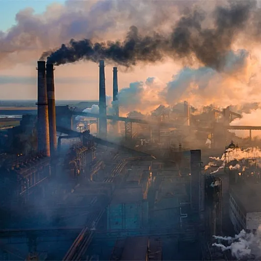
Emissions from coking processes mainly contain ammonia (NH₃), hydrogen sulfide (H₂S), and sulfur dioxide (SO₂). The concentrations of these pollutants remain relatively stable over the production cycle, facilitating the design of treatment systems. To meet strict emission standards, downstream desulfurization and denitration processes are often implemented based on environmental regulations and operational needs.
- Characteristics of waste gas: the waste gas contains ammonia, hydrogen sulfide and sulfur dioxide, and the concentration of waste gas is relatively stable. The rear end is required according to needs conduct desulfurization and denitration treatment
- Source of waste gas: waste gas from desulfurization section, waste gas from ammonium sulfate section and waste gas from salt extraction section
- Waste gas components: ammonia, hydrogen sulfide, sulfur dioxide, nitrogen oxides, particulate matter and VOCs
- Process scheme: pretreatment + RTO + (optional SCR + desulfurization)
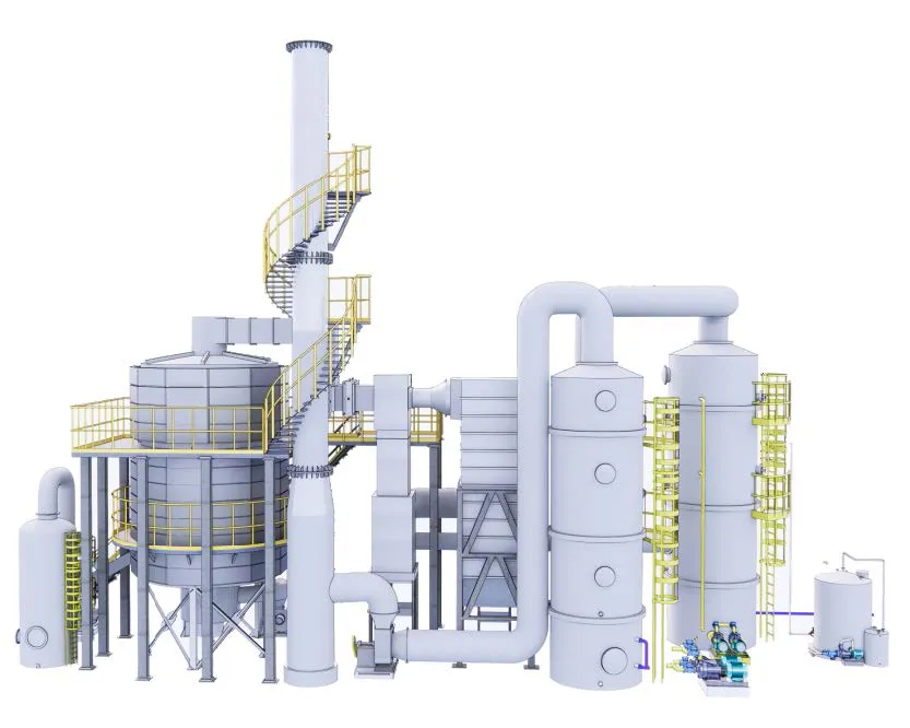
Coking industry 3D drawing
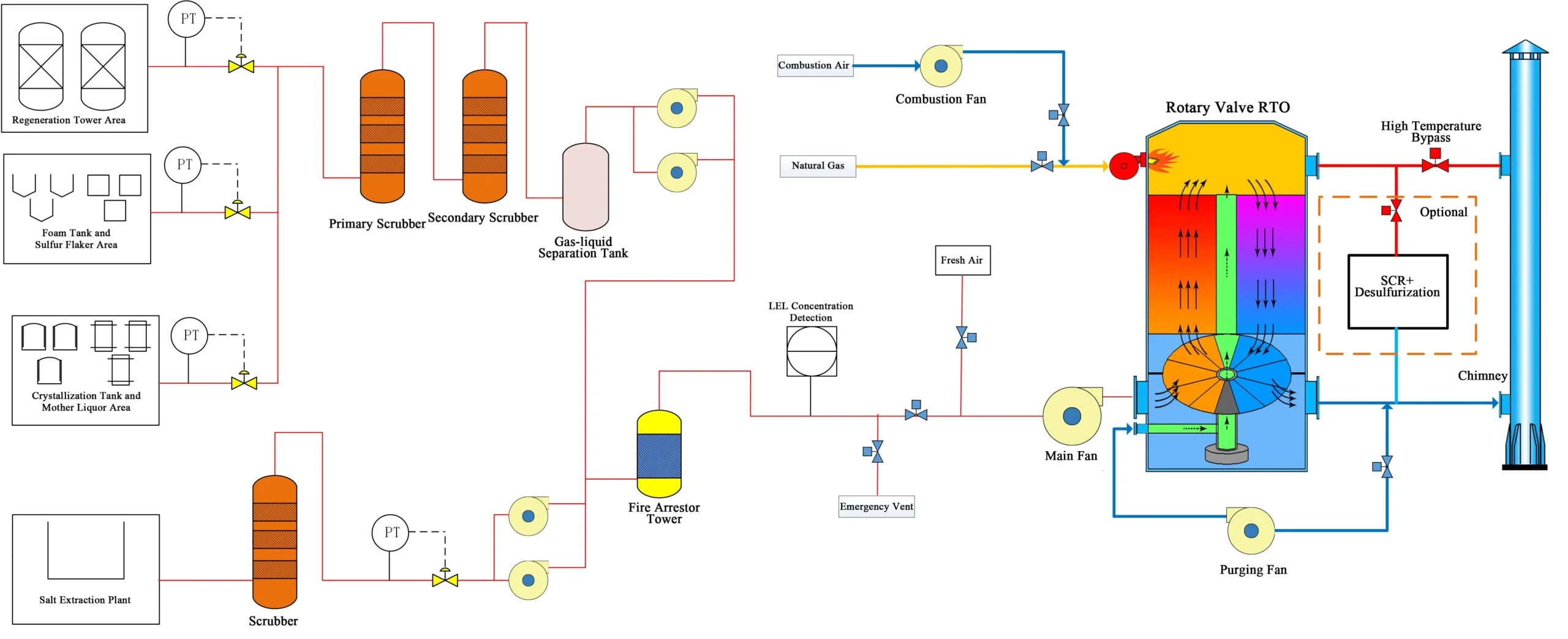
Process flow chart of VOCs treatment in Coking Industry
Process Scheme
To effectively manage and treat waste gas from coking operations, a multi-stage treatment system is proposed:
- Pretreatment: The initial phase involves conditioning the waste gas by removing large particulates and adjusting temperature and humidity. This ensures optimal operating conditions for downstream processes and improves overall treatment efficiency.
- Regenerative Thermal Oxidation (RTO): As the core degradation step, the waste gas is heated to temperatures ranging from 760°C to 870°C, oxidizing organic pollutants into carbon dioxide (CO₂) and water vapor (H₂O). This process effectively destroys VOCs and other organic emissions.
- Targeted Post-Treatment: Depending on regulatory and operational requirements, additional processes such as Selective Catalytic Reduction (SCR) may be incorporated to reduce NOx emissions using ammonia or urea, followed by desulfurization to remove sulfur compounds via reagents such as limestone. These steps enhance compliance with stringent emission standards.
By adopting this integrated treatment approach, the coking industry can achieve significant reductions in emissions, ensuring environmental compliance and minimizing ecological impact.
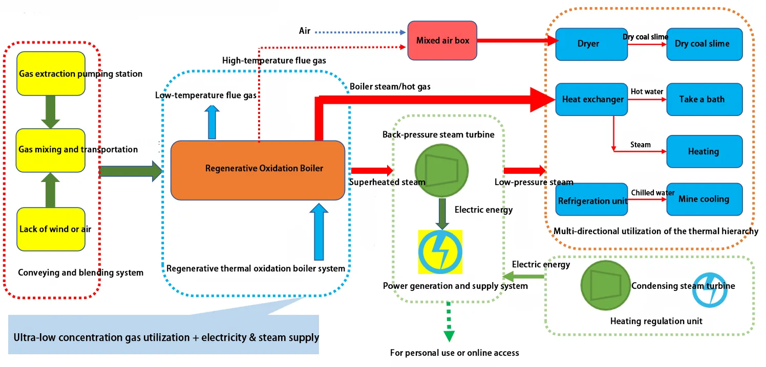
Thermal storage oxidation heat energy cascade utilization technology route
Key Technologies of Thermal Storage Oxidation Equipment
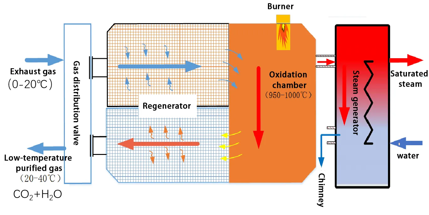
Thermal Storage Oxidation Boiler Technology Principle
The thermal storage oxidation boiler “stores” the heat generated during the combustion of exhaust gas and then outputs it as high-temperature flue gas. Its heat conversion efficiency reaches as high as 99%, and its overall thermal efficiency exceeds 97%, enabling efficient recycling of the heat energy carried by the exhaust gas.
System Thermal Stability Technology
Maintaining system thermal stability under the influence of boundary conditions such as coal mining and tunneling disturbances, coalbed methane concentration disturbances, gas transportation system equipment disturbances, instrument zero drift, large inertia of thermal storage bodies, boiler vaporization inertia, and changes in heat load.
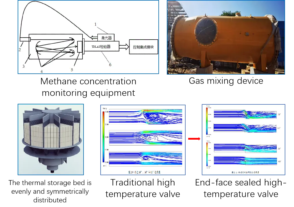
Intelligent Safety System
To tackle the high degree of coupling among system parameters, we have designed a multi-constraint real-time optimization control program to keep the entire system operating safely and efficiently. Each system also undergoes condition-specific HAZOP analysis to ensure safety, reliability, and fail-safe operation.
| System Safety Technologies | |||||||
| Hardware Category | Software/Program Category | ||||||
| 1 | Methane Concentration Monitoring | 7 | Dual Valve Control | 1 | APP Remote Monitoring | 7 | Anomaly Alarm |
| 2 | Flame Arrestor Facilities | 8 | Dual Gas Control | 2 | Exhaust Temperature Control | 8 | Smart Interlocking |
| 3 | Explosion Venting Facilities | 9 | Flame Monitoring Facilities | 3 | Waste Heat Recovery Control | 9 | Fault Auto-stop |
| 4 | Overtemperature Emergency Vent Valve | 10 | Ignition Facilities | 4 | Combustion Temperature Control | 10 | Equipment Self-check Program |
| 5 | Emergency Vent Valve | 11 | Safety Valve | 5 | Equipment Temperature Difference Monitoring | 11 | Power-off Control |
| 6 | Concentration Regulation Facilities | 12 | Explosion-proof Control Components | 6 | Emergency Stop Control | 12 | System Integration Solution |
Thermal Storage Ceramics
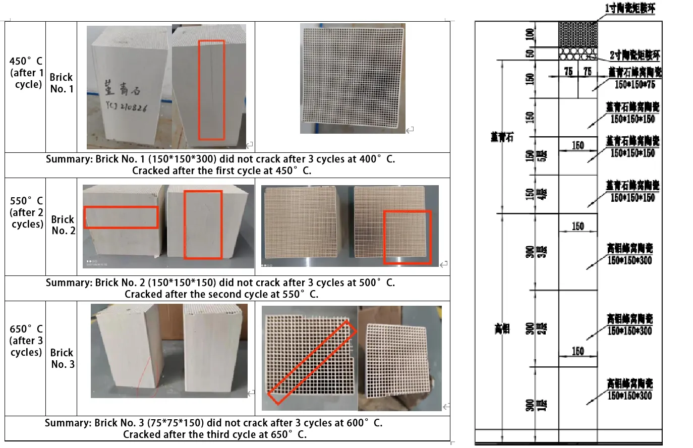
1. Selection and layout
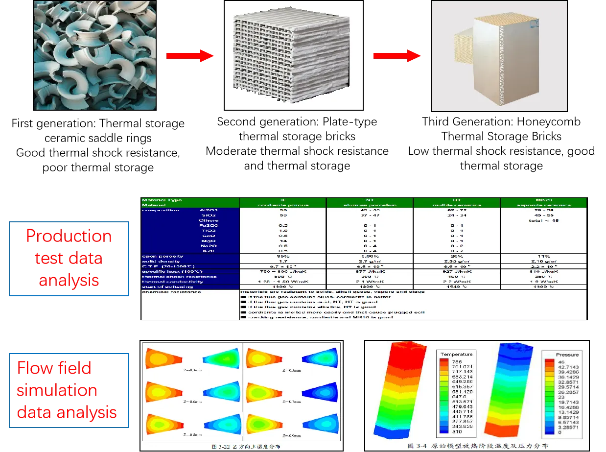
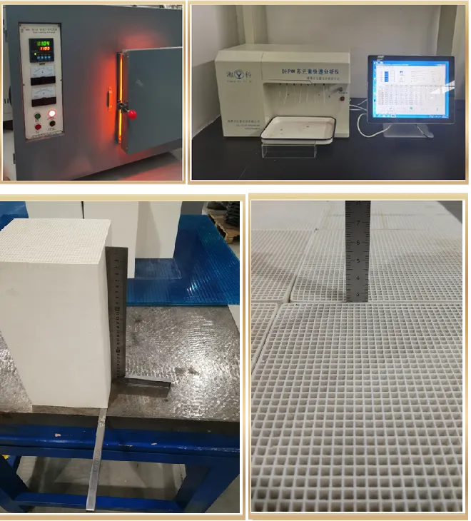
2. Performance testing
3. Thermal shock testing
Insulation Materials
1. Performance testing
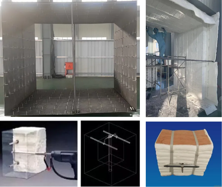
Upon arrival, the insulation foam undergoes inspections focusing on key indicators such as dimensions, bulk density, resilience, tensile strength, and chemical composition.

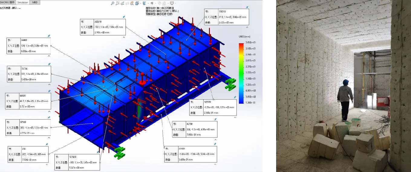
2. High-volume, high-temperature flue manufacturing
Design Features:
- Stable and sturdy structure, ensuring long-term insulation modules remain in place
- Reliable insulation and stable heat supply
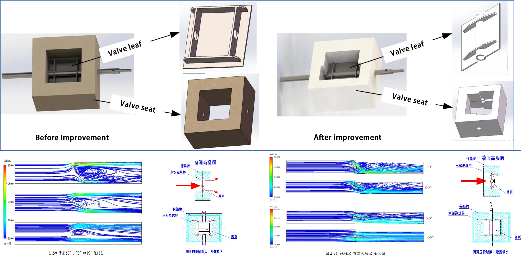
Large Flow End Face High Temperature Valve
New air-cooled, high-temperature end-face valve:
- Maximum temperature resistance 1100°C
- Reduces leakage
- Reduces resistance coefficient
- Increases flow capacity
- Improves safety
