직접 발사 열산화제 (에게)
고농도, 저용량, 고도로 복잡한 산업 폐가스 처리를 위해 특별히 설계되었습니다. 고전적인 "3T" 연소 원리를 활용하여 최대 99.99%의 절대적인 파괴 제거 효율(DRE)을 제공하며, 촉매 독소나 중입자에 대한 내성을 유지합니다.
문의하기Direct-Fired Thermal Oxidizer (TO)
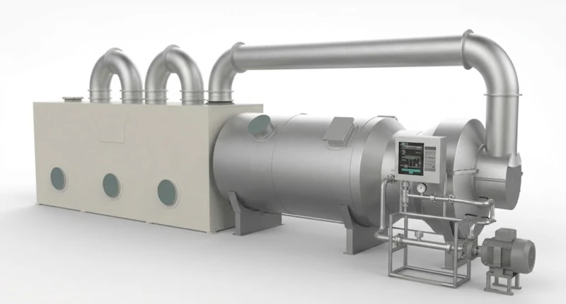
Direct-fired waste gas incinerators are key equipment in organic waste gas incineration treatment systems. The design principle of waste incinerators is to ensure that the waste is completely burned in the furnace at the specified incineration temperature and with sufficient residence time.
Waste incinerators are divided into two types: vertical and horizontal. The cylindrical incinerator consists of a furnace shell, furnace lining, rain shield (determined according to specific needs), etc. The incinerator shell is usually made of Q345R material. The furnace body is designed with observation ports, thermocouple conduits, pressure taps, and other accessories. These accessory conduits are made of high-temperature-resistant stainless steel. The observation ports are equipped with sight glass ball valves to safely isolate the furnace flue gas from escaping.
In high-temperature process gas flow, methods for uniform distribution of the gas flow are considered. Special designs are implemented for the furnace interior, including uniquely shaped flow-straightening rings and checker walls as flow-equalizing measures. These methods result in minimal increases in equipment pressure loss and are highly practical.
The details are as follows: The flow-straightening rings are installed at specific positions in the front section of the incinerator to rationally form a combustion dynamic field, enhancing the thorough mixing and combustion of the gas flow inside the furnace. The checker walls ensure the gas flow enters the furnace evenly and mixes uniformly with the flue gas, leading to more complete reactions. Additionally, they serve a heat storage function, efficiently utilizing the furnace temperature.
The checker walls are constructed with square bricks, featuring central circular holes and dry masonry for stable structure. The bottom adopts an arched hole structure, which can also function as a manhole. The arched holes can be sealed with checker bricks during operation to ensure uniform flue gas flow.
Product
Structure
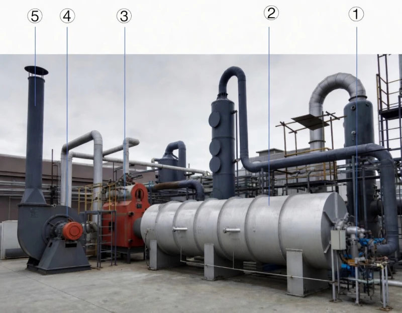
연소기
열 산화 장치(TO)
Heat Exchanger /
Waste Heat Boiler
Fan
Chimney
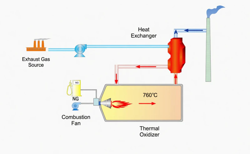
How the TO Process Works (Thermal Oxidation Principles)
Introduction & Mixing
VOC-laden exhaust gas is drawn into the combustion chamber by a system fan. A portion of this gas may even be used directly as combustion air for the burner.
Direct Combustion
The burner (typically fueled by natural gas or fuel oil) ignites, rapidly heating the mixed gas to the target temperature (e.g., 850°C).
Retention
The gas remains in the refractory-lined reaction chamber for a specific residence time, ensuring that complex organic molecules are 100% thoroughly oxidized.
Heat Recovery & Exhaust
The resulting high-temperature, clean exhaust gas can be discharged directly through a stack, or routed through an external heat exchanger (such as a shell-and-tube heat exchanger or waste heat boiler) to generate hot water, steam, or thermal oil for other plant processes.
주요 특징 및 장점
Low CapEx
Extremely simple structure without complex ceramic media, pneumatic switching valves, or expensive catalysts, leading to minimal initial investment.
Superior Adaptability
Immune to dust clogging and catalyst poisons (Si, S, P, Halogens). Capable of simultaneous waste gas and liquid processing.
Maximum Efficiency
Achieves up to 99.99% DRE. The ultra-high temperature environment ensures the destruction of even the most refractory organic compounds.
Compact & Low Maintenance
Minimal moving parts ensure high reliability. The equipment footprint is significantly smaller than RTO and RCO systems.
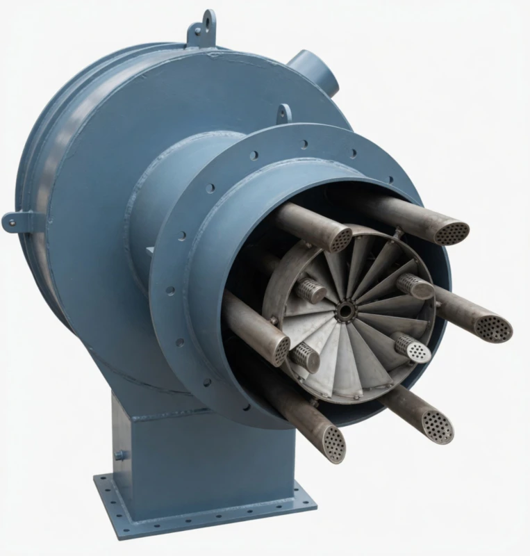
Core Component: High-Efficiency Burner
⚙️ The Heart of the Incineration Process
The burner mainly consists of the burner body, flame stabilization device, air distributor, ignition gas gun, main gas gun, explosion-proof high-energy ignition device, and flame detection equipment.
🌪️ Advanced Vortex Flow Pattern
The most notable feature of our high-efficiency burner is that the swirling mixed airflow forms a low-pressure zone in the center of the combustion chamber. This draws part of the flue gas back, prolonging the residence time of the fuel and ensuring complete combustion. The thorough mixing accelerates the reaction rate, shortening the flame length. This intense mixing and stable flame root prevent flame instability and incomplete combustion issues across various fuels.
🔥 Two-Stage Ignition & Precise Control
The burner adopts a two-stage ignition method (ignition gun → ignition gas gun → main gas gun). It features a compact structure, stable combustion, a high turndown ratio, and low noise. The central air supply is equipped with a flame stabilization shield to create a recirculation zone. Additionally, it is equipped with a viewing port to observe the combustion status and an automatic or manual air damper at the inlet.
-2.webp)
Selection Guide
(When to Choose TO over RTO/CO)Addressing the most common customer concern: Since Thermal Oxidizers (TO) have relatively higher operational energy consumption, why are they still the absolute best choice under certain conditions?
High-Concentration Exhaust
When the exhaust gas concentration is extremely high, approaching or reaching 25% of the Lower Explosive Limit (LEL). Under these conditions, the TO can sustain combustion without additional fuel and can even generate significant byproduct steam via a waste heat boiler.
Presence of Catalyst Poisons
When the exhaust contains large amounts of sulfides, halogens (e.g., Teflon production exhaust), or heavy metals. These substances instantly poison and disable CO/RCO catalysts, whereas the TO's pure high-temperature thermal combustion remains completely unaffected.
High Dust or Tar Content
Exhaust gases with high particulate matter or sticky substances easily clog the honeycomb ceramic media in RTOs, causing safety hazards and high cleaning costs. The straight-through, unobstructed structure of a TO effortlessly handles these harsh conditions.
Low Volume & Intermittent Production
RTO/RCO systems are bulky, slow to heat up, and cumbersome to shut down, making them unsuitable for frequent starts and stops. In contrast, the TO starts rapidly and features a simple structure, making it ideal for non-continuous, small-scale exhaust sources.
Ideal Applications
(Industries & Typical Scenarios)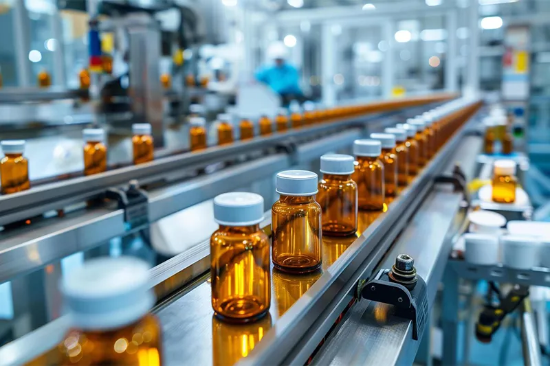
Chemical & Pharmaceutical
Perfect for batch processes and exhaust streams containing halogens, sulfides, or catalyst poisons that would rapidly destroy standard RTO/RCO ceramic media and catalysts.
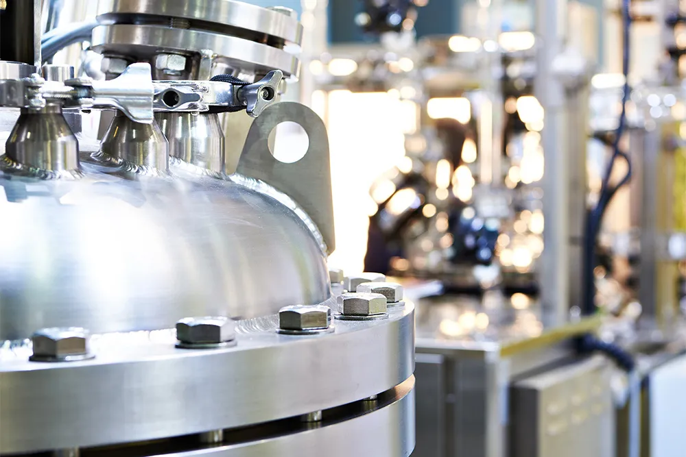
Petrochemical & Oil/Gas
Safely and efficiently handles highly fluctuating gas volumes and extremely high VOC concentrations (approaching LEL limits). Capable of utilizing high heat values to generate byproduct steam.
Hazardous Waste Processing
Ideal for harsh environments with high particulate matter, sticky residues (tar), or scenarios requiring the simultaneous incineration of both highly-polluted gas and liquid waste.
What Our Clients Say
(Trusted by Industry Leaders)"We process exhaust gases with high concentrations of halogens that previously destroyed our RTO media within months. Since switching to this Thermal Oxidizer, our downtime has dropped to zero. The straightforward design is an absolute lifesaver for our chemical plant."
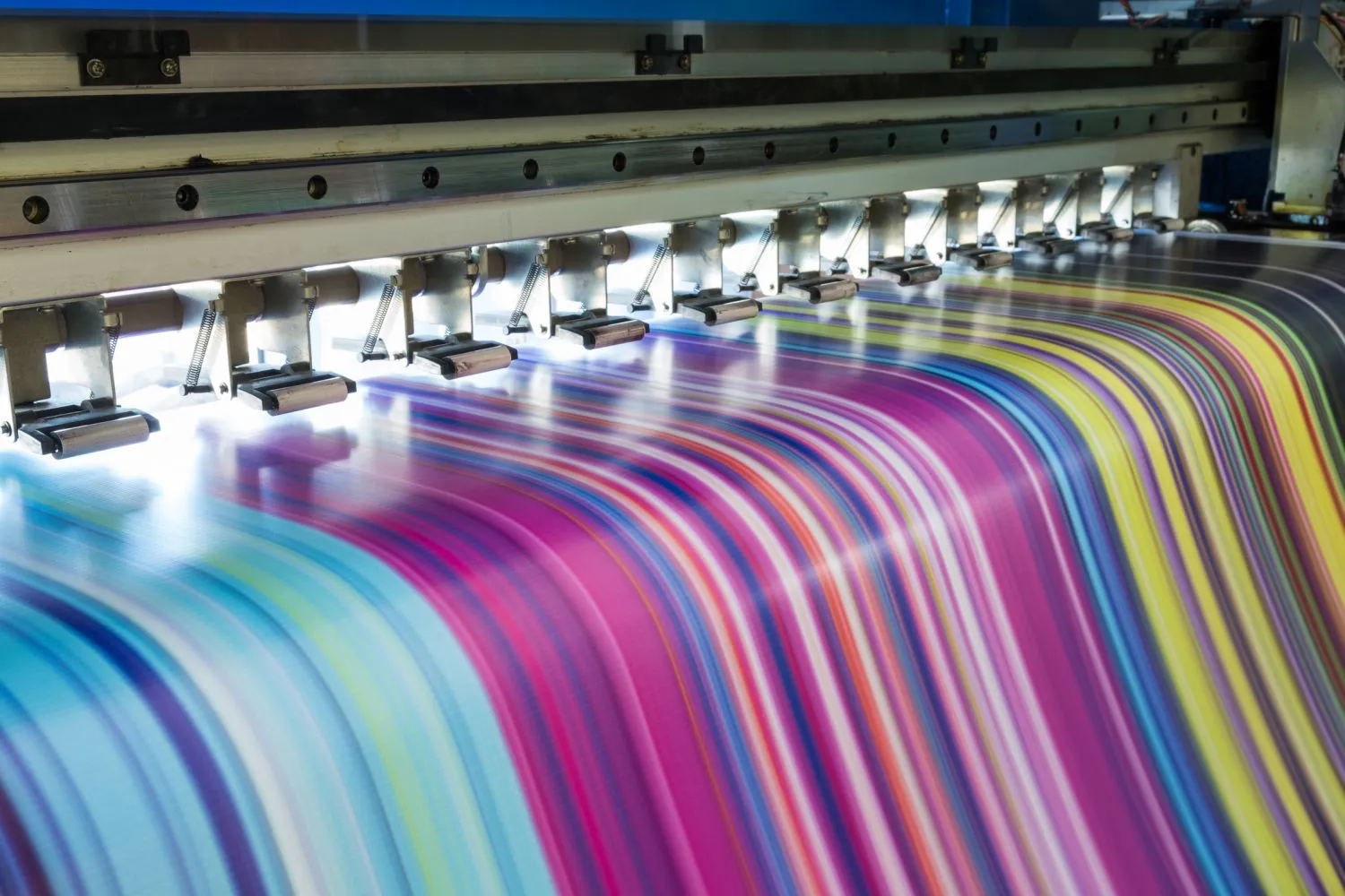
"The intermittent nature of our specialty coatings production made traditional RTOs too expensive to keep heated. This TO unit fires up rapidly, handles our batch processes perfectly, and the heat recovery boiler generates enough steam to offset our fuel costs."
"Outstanding destruction efficiency. We needed 99.99% DRE to meet strict new environmental regulations for our highly concentrated VOC streams. The high-efficiency burner performs exactly as promised, and maintenance is incredibly simple."


