Case Study · Industrial Emission Control
How a leading steel producer achieved 99.7% desulfurization efficiency, SO₂ outlet below 10 mg/Nm³, particulate matter below 3 mg/Nm³, and complete white plume elimination from 90,000 Nm³/h of rotary kiln off-gas — deploying an integrated five-stage treatment system with MGGH heat exchange for energy-efficient plume suppression and real-time intelligent monitoring for adaptive pollution control.
MGGH Heat Exchange
습식 정전기 집진기
Limestone-Gypsum FGD
White Plume Elimination
01 — Industry Background
Steel Production, Electric Arc Furnace Dust, and the Ultra-Low Emission Transformation
In the steel manufacturing process, by-products and particulate matter are generated at multiple production stages — most notably at the sintering, smelting, and electric arc furnace stages where high-temperature metallurgical reactions drive the release of fine metallic oxide dust. Electric arc furnace (EAF) dust, in particular, accounts for 12–20 kg of dust per tonne of steel produced, with zinc oxide content often exceeding 40%. When combined with dust from power generation, heavy vehicle transportation, and ship operations, steel plant emissions create significant environmental pollution challenges that directly affect the health of communities near industrial clusters.
Effective management of EAF dust is therefore not only an environmental compliance obligation but also a resource recovery opportunity: the dust contains significant concentrations of zinc, lead, and other metals that represent commercial value when processed through the appropriate recovery chain. The rotary kiln process described in this case study is the primary industrial-scale technology for processing EAF dust and recovering zinc and iron from the dust while generating kiln off-gas that requires comprehensive multi-pollutant treatment.
The facility in this project operates a rotary kiln for EAF dust processing, producing 56,890 Nm³/h of standard flue gas (90,213 Nm³/h at process conditions) at 150–160°C. The facility has built an environmental control and management integrated intelligent platform, installing air micro-stations and total suspended particulate concentration monitoring instruments to achieve full-coverage real-time stack monitoring, early warning, and intelligent coordinated management. These measures have significantly elevated the facility’s environmental management standard, achieving ultra-low emission compliance.
The project targets the Ultra-Low Emission Standards for Steel Industry Air Pollutants under EU IED BAT conclusions for iron and steel production, which require SO₂ ≤20 mg/Nm³, particulate matter ≤5 mg/Nm³, CO ≤100 mg/Nm³, HCl ≤5 mg/Nm³, and HF ≤20 mg/Nm³. The project has substantially exceeded these targets, achieving actual outlet concentrations well below all limits.
.webp)
“The rotary kiln EAF dust processing off-gas is distinctive in that SO₂ at 2,800 mg/Nm³ must be reduced to below 20 mg/Nm³ — a 99.3% reduction requirement — while simultaneously managing high dust loading, CO, HCl, HF, and the persistent white plume from high-humidity post-scrubber exhaust. The MGGH heat exchange approach to white plume elimination avoids the energy penalty of conventional gas reheating while exploiting the facility’s own waste heat as the energy source for plume suppression.”
— Engineering Technical Summary, Steel Industry Dust Removal and Desulfurization Project
02 — Pollution Profile
Rotary Kiln EAF Dust Processing Off-Gas: High SO₂, High Dust, CO, HCl, HF, and White Plume
The rotary kiln is fired by natural gas (fuel consumption approximately 5,500 m³/h). Process conditions at the kiln exit generate 90,213 Nm³/h of off-gas at 150–160°C. At the standard reference condition (15% O₂, dry basis) this corresponds to 56,890 Nm³/h. The off-gas carries the following simultaneous pollutant categories:
- SO₂ at 2,800 mg/Nm³ at desulfurization inlet: Generated from sulfur compounds in the EAF dust feed material and from the combustion gases. After the washing tower pre-treatment, SO₂ enters the FGD absorber at 2,800 mg/Nm³. Target outlet: ≤20 mg/Nm³ (designed) / actual achieved: 10 mg/Nm³. Desulfurization efficiency: 99.3% design / 99.7% actual.
- Particulate matter (PM) at 100 mg/Nm³ initial: Fine metallic oxide and carbon particulates from the EAF dust feed and rotary kiln combustion zone. After washing tower pre-treatment, the FGD absorber inlet PM is significantly reduced. Remaining fine particles are captured by the wet electrostatic precipitator at ≥95% efficiency. Target outlet: ≤5 mg/Nm³ (designed) / actual: 3 mg/Nm³. Overall system dust removal: 75% design / 90% actual.
- CO at 4,000 mg/Nm³ initial: Present from incomplete combustion in the rotary kiln. Significant CO concentration requires CO monitoring upstream and system safety interlocks, as well as confirming adequate dilution air mixing before the system reaches enclosed treatment zones.
- HCl at 15 mg/Nm³ and HF at 50 mg/Nm³ initial: Acid gases from chloride and fluoride compounds in the EAF dust feed. Captured by the washing tower scrubbing and the FGD limestone-gypsum absorption stages. Outlet: HCl ≤2 mg/Nm³ actual (design limit 5), HF ≤6 mg/Nm³ actual (design limit 20).
- Corrosive substances at 30 mg/Nm³ NaCl: Alkali metal chloride from the EAF dust processing creates a corrosive environment for all wetted treatment equipment. Material specifications must account for this combined acid gas and alkali salt service environment.
- Visible white plume: Post-scrubber exhaust at approximately 50°C (at the FGD outlet) is saturated with water vapor. Without active plume suppression, a visible white plume is generated under most ambient conditions. The MGGH (Mist Generation and Gas Heating, i.e. Gas-Gas Heat Exchanger) system uses hot raw kiln off-gas to reheat the post-FGD clean gas to above 90°C, raising the stack discharge temperature above the atmospheric dew point and eliminating visible plume formation without external energy input.
| 매개변수 | Initial / FGD Inlet | Designed Outlet | Actual Outlet | EU IED Limit |
|---|---|---|---|---|
| SO₂ | 2,800 mg/Nm³ | ≤20 mg/Nm³ | 10 mg/Nm³ | 20mg/Nm³ |
| Particulate matter (PM) | 100 mg/Nm³ | ≤5 mg/Nm³ | 3 mg/Nm³ | 5 mg/Nm³ |
| CO | 4,000 mg/Nm³ | ≤100 mg/Nm³ | ≤100 mg/Nm³ | 100 mg/Nm³ |
| 염산 | 15 mg/Nm³ | ≤5 mg/Nm³ | 2 mg/Nm³ | 5 mg/Nm³ |
| HF | 50 mg/Nm³ | ≤20 mg/Nm³ | 6 mg/Nm³ | 20mg/Nm³ |
| Visible white plume | Present | None (invisible) | None — confirmed | No visible white plume |
| Process flue gas volume | 90,213 Nm³/h | — | — | — |
| Standard flue gas volume | 56,890 Nm³/h | — | — | — |
| Flue gas temperature (kiln exit) | 150–160°C | — | — | — |
| Corrosive substances (NaCl) | 30 mg/Nm³ | — | — | — |
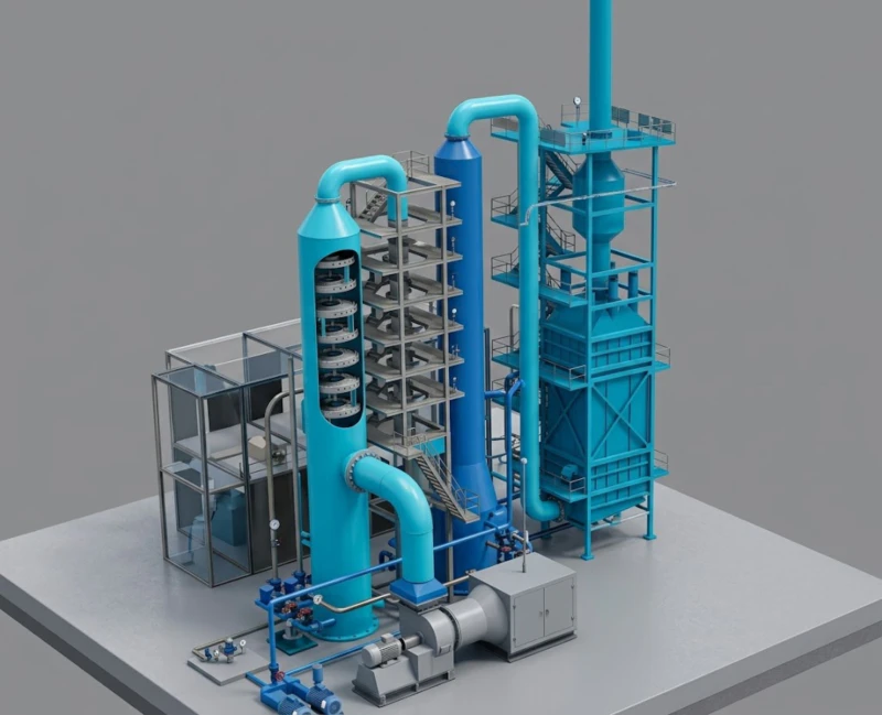
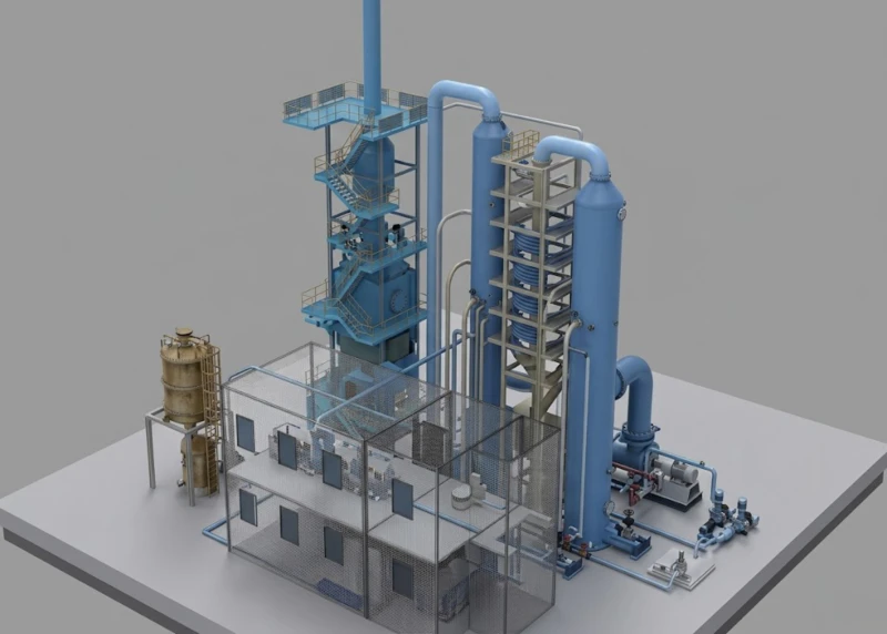
03 — Treatment Solution
Five-Stage Treatment System: MGGH Pre-Cooling, Washing Tower, FGD, Wet ESP, and MGGH Reheating
The treatment system exploits the facility’s own hot kiln off-gas as the energy source for both pre-cooling (before the scrubber) and reheating (after the scrubber) through a MGGH (Gas-Gas Heat Exchanger) system — recovering waste heat for both thermal management of the treatment chain and for white plume elimination without any external energy input for gas reheating. This energy self-sufficiency distinguishes the MGGH approach from conventional gas reheating using steam or electric heaters.
Stage 1: MGGH Pre-Cooling Heat Exchanger (160°C → 115°C)
Hot raw kiln off-gas at 160°C enters the MGGH pre-cooling heat exchanger (flue gas volume 52,320 m³/h; heat transfer area 400 m²; hot side inlet 160°C; hot side outlet 115°C; hot water inlet 89°C; hot water outlet 109°C; device dimensions 3,000×2,120×3,524 mm). This pre-cooling step serves two purposes: it reduces the gas temperature to a level compatible with anti-corrosion materials in the downstream washing tower and FGD scrubber, and it recovers thermal energy into the hot water circuit that is later used to reheat the post-FGD clean gas for white plume elimination. MGGH heat exchangers must be manufactured from appropriate stainless steel grades to avoid corrosion, leakage, and sludge deposition issues; selecting the right stainless material grade, setting appropriate gas velocity, and optimising duct geometry to reduce deposit rate are the key design disciplines for MGGH longevity.
Stage 2: Washing Tower (HCl Pre-Scrubbing and PM Pre-Removal)
The pre-cooled gas enters the washing tower (process flue gas volume 80,841 m³/h; inlet temperature 115°C; outlet temperature 65°C; gas velocity 2.4 m/s; tower internal diameter φ3.5 m; 2 spray layers; single pump flow 80 m³/h; tower height 23 m). The washing tower has three layers of spray nozzles that effectively wash out HCl acid gases from the flue gas. After washing, the gas temperature drops and proceeds into the desulfurization system for FGD treatment. The tower pre-removes HCl to protect the limestone FGD slurry from chloride contamination that would otherwise impair the slurry’s SO₂ absorption chemistry and gypsum crystallisation quality. The key to washing tower operation is ensuring the circulating water is properly managed: monitoring pH continuously and controlling the chloride concentration in the circulating liquor to prevent it from rising to levels that reduce HCl absorption efficiency.
Stage 3: Limestone-Gypsum FGD Absorber Tower (φ2.8 m, 70,500 Nm³/h)
After the washing tower, the gas enters the limestone-gypsum FGD absorber for SO₂ removal. Key parameters: flue gas volume 70,500 m³/h at FGD inlet; flue gas temperature 65°C; SO₂ inlet concentration 2,800 mg/Nm³; SO₂ outlet concentration 20 mg/Nm³ (design) / 10 mg/Nm³ (actual); calcium-to-sulfur molar ratio 1.05; gas velocity <3.2 m/s; tower internal diameter φ2.8 m; liquid-to-gas ratio 22.8; 4 spray layers; single pump flow 325 m³/h; slurry settling time 3.5 h; limestone operating consumption 275 kg/h; gypsum production 395 kg/h; gypsum moisture content 12–15%; mist eliminators: 2-layer screen type (first stage) + 1 tube-type (second stage); limestone storage capacity 30 m³ (4.5-day autonomy). The limestone-gypsum process achieves 99.3% design SO₂ removal efficiency (99.7% actual) and simultaneously captures a significant fraction of the residual HF from the gas stream through calcium fluoride formation in the slurry.
Stage 4: Wet Electrostatic Precipitator (WESP, 70,500 Nm³/h)
Post-FGD gas enters the WESP for deep PM polishing and acid mist capture. Key parameters: flue gas volume 70,500 m³/h; flue gas temperature 65°C; design wash velocity 1.4 m/s; anode tube effective collection area 14.16 m²; collection area 943.5 m²; outlet PM concentration ≤5 mg/Nm³; body resistance 300 Pa; anode tube specifications φ360×6,000 mm; number of anode tubes 128; cathode wire count 2,205; energisation type high-frequency power; electrical parameters 72 kV / 800 mA; specific collection area 37 m²/(m³·s). The WESP achieves ≥95% purification of residual fine particulates and acid mist that pass through the FGD mist eliminators, delivering outlet PM at 3 mg/Nm³ (actual) against the 5 mg/Nm³ design target.
Stage 5: MGGH Reheating Heat Exchanger (50°C → 90°C)
The clean post-WESP gas at approximately 50°C is reheated to 90°C by the MGGH reheating heat exchanger (flue gas volume 53,366 m³/h; heat transfer area 812 m²; device pressure drop 370 Pa; flue gas inlet 50°C; flue gas outlet 90°C; hot water inlet 108°C; hot water outlet 90°C; device dimensions 3,000×2,120×4,004 mm). By raising the stack discharge temperature to 90°C — above the atmospheric dew point under all normal operating conditions — the visible white plume is eliminated without any external energy input. The hot water used to reheat the clean gas is the same hot water heated by the raw gas in the upstream MGGH pre-cooling stage, creating a fully self-contained heat recovery loop.
Kiln
160°C
Pre-Cool
160→115°C
Tower
HCl/PM
Limestone
99.3% SO₂
PM+Mist
≥95%
Reheat
50→90°C
→ Stack
No Plume
⭐ New or upgraded equipment in this project
.webp)
04 — Core Advantages
Why MGGH + Wet ESP Is the Optimal Architecture for Steel Rotary Kiln Off-Gas
- ✓
MGGH Energy Self-Sufficiency: White Plume Elimination Without External Energy Input: The defining advantage of the MGGH approach to white plume elimination is that it uses the facility’s own waste heat — extracted from the hot raw kiln off-gas in the pre-cooling stage — as the energy source for post-FGD gas reheating. The hot water heated from 89°C to 109°C in the pre-cooling MGGH carries the same thermal energy that is used to raise the post-WESP gas from 50°C to 90°C in the reheating MGGH. No steam, electric heaters, or natural gas burners are required for gas reheating. Compared with direct gas-to-gas heat exchange using hot raw gas, the hot water intermediary avoids cross-contamination risks between clean and raw gas streams and provides better thermal control through the water circuit flow rate regulation. - ✓
99.7% Actual SO₂ Removal from 2,800 mg/Nm³ to 10 mg/Nm³ — Far Below the 20 mg/Nm³ Ultra-Low Limit: The verified actual SO₂ removal efficiency of 99.7% (outlet 10 mg/Nm³ vs. design target 20 mg/Nm³ and limit 20 mg/Nm³) delivers a 50% compliance margin below the ultra-low limit. This robust performance results from the combination of the washing tower pre-scrubbing (which removes HCl that would otherwise compete with SO₂ for limestone absorption capacity) and the optimised FGD tower design (4 spray layers, L/G ratio of 22.8, calcium-to-sulfur ratio of 1.05, 325 m³/h single pump flow). The washing tower’s HCl pre-removal is particularly important for limestone FGD performance at high-SO₂ inlet conditions. - ✓
Washing Tower HCl Pre-Scrubbing Protects FGD Chemistry and Gypsum Quality: The washing tower serves a dual purpose: it removes a significant fraction of HCl from the gas before it enters the FGD absorber, and it reduces gas temperature from 115°C to 65°C to protect the FGD absorber internals and slurry chemistry. The HCl pre-removal prevents chloride accumulation in the FGD slurry loop, which would otherwise impair gypsum crystallisation quality (chloride-contaminated gypsum cannot be reused as a construction material) and reduce SO₂ absorption efficiency by competing for lime absorption capacity. For steel rotary kiln off-gas applications where both HCl and high SO₂ are simultaneously present, the two-stage washing tower + FGD architecture is superior to a single-stage all-in-one scrubber. - ✓
Intelligent Monitoring Platform Enables Adaptive Control Across Variable Kiln Operating Conditions: The facility’s integrated environmental control and management intelligent platform, with air micro-stations and total suspended particulate monitoring, provides full-coverage real-time stack and environment monitoring. This real-time data feeds directly into an adaptive control algorithm that adjusts limestone slurry dosing rates, washing tower circulating pump speeds, and WESP energisation levels in response to detected fluctuations in SO₂, PM, and temperature. The intelligent platform significantly elevates the facility’s environmental management capability and is a key enabler of the consistent ultra-low performance achieved in practice versus the designed levels. - ✓
Gypsum By-Product from FGD Enables Circular Economy and Zero Secondary Solid Waste: The FGD stage produces gypsum at 395 kg/h (maximum) with moisture content of 12–15%. This gypsum meets the quality specification for construction material reuse (wallboard substrate, cement additive) when the chloride content is confirmed below EN 13279-1 threshold levels (protected by the upstream washing tower HCl pre-removal). The gypsum by-product eliminates the solid waste disposal cost and environmental liability that would arise from treating calcium sulfate as waste, and contributes to the facility’s “green, clean, low-carbon” development objectives. - ✓
Modular Design Accommodates Future Standard Tightening Without Core System Replacement: The five-stage MGGH + washing tower + FGD + WESP + MGGH modular architecture allows individual stage upgrades without replacing the entire treatment system. If future EU IED BAT conclusions tighten SO₂ limits below 10 mg/Nm³, the FGD stage can be upgraded independently (additional spray layer, increased L/G ratio, second-stage absorber). Similarly, if PM limits tighten below 3 mg/Nm³, the WESP energisation can be increased or a second WESP stage added without disturbing the other treatment stages.
05 — Operational Results
Actual Performance: All Six Parameters Substantially Below EU Ultra-Low Limits
Maximum installed equipment power: 850.05 kW; actual operating power: 691 kW. At 24-hour continuous operation and 0.36 RMB/kWh equivalent, the daily electricity cost is 5,970.24 RMB equivalent; at 8,000 annual operating hours the annual electricity cost is approximately 199,008 RMB equivalent. Annual water cost: approximately 4.8 ten-thousand RMB equivalent (3 t/h at 2 RMB/t). Annual limestone cost: approximately 55 ten-thousand RMB equivalent (275 kg/h at 250 RMB/t).
06 — Implementation Cautions
Critical Engineering and Operational Lessons for Steel Rotary Kiln Off-Gas Treatment
- ⚠️
Flue gas temperature and SO₂ fluctuations are the primary operational risk — adaptive control and furnace-to-treatment communication are essential: The primary documented risk is that flue gas temperature and SO₂ concentration fluctuations cause system discharge instability. For steel rotary kilns processing EAF dust, the zinc and sulfur content of the dust feed varies between batches, creating significant SO₂ concentration variability at the kiln exit. Implement a formal protocol for advance notification from the kiln operations team to the treatment system control room before any planned changes to the dust feed composition or kiln operating temperature set-points, enabling proactive adjustment of limestone dosing rates before the concentration change enters the FGD absorber. - ⚠️
Upstream dust pre-treatment equipment failure easily causes MGGH heat exchanger fouling and blockage — install an online PM monitor at the MGGH inlet: The second documented risk is that upstream gas dust pre-treatment equipment failure leads to elevated dust loading entering the MGGH heat exchanger, causing progressive fouling and blockage of the heat exchanger passages. Install an online PM concentration monitor at the MGGH inlet (at the MGGH pre-cooling heat exchanger entrance temperature reduction position) with an alarm threshold set below the level at which fouling rate becomes significant. When the alarm triggers, initiate the MGGH soot blowing cleaning system and investigate the upstream dust pre-treatment for the cause of elevated loading. Also configure the MGGH soot blowing system for periodic automatic operation during normal operation, not only on-demand response to alarms. - ⚠️
Production process pipe leaks cause wastewater overflow incidents — weekly piping inspections are mandatory: The corrosive gas environment and wide temperature cycle range create significant mechanical stress on all wetted piping. The third documented risk is that pipe leaks during production cause waste water overflow. Implement a weekly visual inspection programme covering all pipe joints, valve glands, pump seal faces, expansion joint bellows, and condensate drain connections. Maintain a spare parts inventory for all standard pipe sections and sealing components. The emergency response procedure for any detected leak must include immediate isolation of the affected section and inspection of downstream equipment for contamination before restart. - ⚠️
Equipment and duct corrosion from high-corrosivity gas reduces structural strength — specify the correct stainless steel grade for each section: The fourth documented risk is that the high-corrosivity gas and duct environment progressively reduces equipment structural strength. The combination of HCl, SO₂, HF, NaCl alkali salts, and condensate at temperatures that cycle above and below the acid dew point creates a multi-acid, multi-chloride corrosion environment. For the MGGH heat exchanger specifically, selecting the appropriate stainless steel grade (typically 316L or duplex 2205 for severe chloride service), setting the gas velocity within the design range to minimise erosion-corrosion, and optimising the duct flow cross-section to reduce sludge deposition rate are the key material and design disciplines that determine MGGH longevity. Annual thickness measurement inspection of duct wall and MGGH tube wall is recommended from year 3 onward. - ⚠️
Washing tower circulating water chloride concentration must be actively controlled — install a continuous conductivity analyser: The washing tower scrubs HCl from the gas into the circulating water. If the circulating water chloride concentration is allowed to rise unchecked (through evaporation concentration without adequate bleed-and-dilute), HCl absorption efficiency drops as the driving force for absorption decreases, more HCl enters the FGD absorber, and gypsum quality degrades from chloride contamination. Install a continuous conductivity analyser on the washing tower circulating water loop and implement an automatic bleed-and-dilute control loop that maintains chloride concentration below 20,000 mg/L (or as specified by the gypsum quality requirement).
07 — Engineering Takeaways
Four Lessons from This Steel Rotary Kiln Off-Gas Treatment Project
- 1
MGGH heat exchange is the most energy-efficient approach to white plume elimination when waste heat is available at the facility. Steam reheating and electric reheating both impose an ongoing energy cost for white plume elimination. MGGH uses waste heat that would otherwise be rejected to the atmosphere, converting an energy liability into a plume elimination asset at zero marginal fuel cost. For any steel, non-ferrous, or ceramics facility where hot kiln off-gas is available at ≥150°C before the treatment system, MGGH should be evaluated as the preferred white plume elimination technology on both economic and environmental grounds before any externally-energised reheating alternative is specified. - 2
Washing tower HCl pre-scrubbing is not optional for limestone FGD systems treating gas streams containing both HCl and high SO₂. In isolation, the washing tower appears to add capital cost, footprint, and complexity. In context, it protects the limestone FGD slurry from chloride contamination that would impair SO₂ absorption chemistry, reduce gypsum quality below construction material specification, and ultimately require FGD slurry disposal as hazardous waste rather than gypsum reuse as a product. The two-stage washing tower + FGD architecture has a lower total lifetime cost than a single-stage system that must manage all pollutants simultaneously, because it protects the FGD chemistry from chloride contamination that is difficult to remedy once established. - 3
The actual-versus-designed performance gap in this project reveals the value of intelligent monitoring and adaptive control. Designed performance: SO₂ outlet 20 mg/Nm³ (99.3% removal), PM outlet 5 mg/Nm³ (75% removal). Actual performance: SO₂ outlet 10 mg/Nm³ (99.7% removal), PM outlet 3 mg/Nm³ (90% removal). The facility’s intelligent monitoring platform — real-time adaptive adjustment of limestone dosing, WESP energisation, and washing tower circulation — consistently delivers performance well above the designed baseline. This demonstrates that the investment in real-time monitoring and adaptive control capability is not just an operational comfort feature; it is a quantifiable performance multiplier that creates additional compliance margin above the designed system level. - 4
SO₂ at 2,800 mg/Nm³ demands a high calcium-to-sulfur ratio (1.05) and high liquid-to-gas ratio (22.8) to achieve ≥99% removal — standard power plant FGD design parameters do not apply. Power plant FGD designs typically use calcium-to-sulfur ratios of 1.02–1.05 and L/G ratios of 8–15 for SO₂ inlet concentrations of 1,000–3,000 mg/Nm³. At 2,800 mg/Nm³, achieving 99.3% removal to ≤20 mg/Nm³ requires pushing both ratios to the higher end of the design envelope, combined with 4 spray layers (versus the typical 3 in power plant applications) and careful optimization of slurry pH, calcium limestone ratio, and gypsum crystallization conditions. The design parameters for steel rotary kiln FGD at high SO₂ inlet concentrations must be independently optimized, not simply copied from power sector FGD design references.
08 — Frequently Asked Questions
Steel Rotary Kiln Dust Removal and Desulfurization: Ten Questions Answered
Questions from environmental permit managers, metallurgical engineers, and sustainability teams at steel manufacturing and EAF dust processing facilities planning ultra-low emission upgrades under EU IED / Dutch Activities Decree requirements.
Ready to Achieve Ultra-Low Steel Industry Emission Compliance?
Explore the Full Range of Industrial Emission Control Solutions
From MGGH-integrated dust removal and desulfurization for steel rotary kilns to regenerative thermal oxidation systems for industrial VOC abatement, our engineering team delivers EU IED–compliant solutions for the most demanding steel industry emission control requirements.


