The chemical manufacturing sector presents some of the most intricate and punishing exhaust gas challenges in the industrial landscape. Standard dry filtration systems fail rapidly when exposed to the sticky tar, volatile aerosols, and dense water mist prevalent in these processing environments. To resolve these critical bottlenecks, our company introduces the Ionization Catcher series. These systems are advanced equipment in the fields of environmental protection and energy recovery, operating at an internationally leading level. Highly versatile and incredibly robust, these systems can be widely used in industries such as chemicals, coking, carbon production, spraying, and printing. They achieve highly efficient treatment of viscous tar and microscopic particulate matter. By integrating design, manufacturing, installation, and commissioning into a unified environmental solution, we ensure continuous, compliant facility operations.
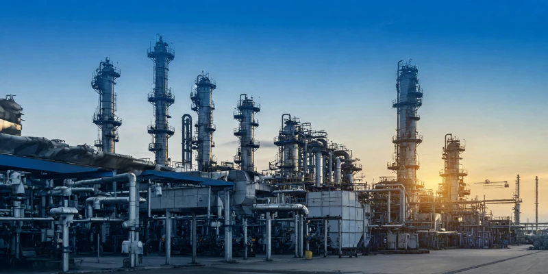
Large-Scale Ionization Catcher Installation in a Chemical Processing Facility
1. The Challenge of Viscous Aerosols and Tar
In chemical, coking, and carbon processing operations, exhaust gases are rarely composed of dry, easily filterable particulate matter. Instead, the gas streams are heavily burdened with a complex, multi-phase mixture of semi-liquid tar, dense water mist, unburned hydrocarbons, and ultra-fine dust. The physical nature of these contaminants creates a profound engineering dilemma that traditional filtration cannot solve.
If these volatile emissions are routed into a standard fabric baghouse, the sticky tar and moisture will instantly blind the microscopic pores of the filter media. The capillary action draws the viscous liquid deep into the fabric, baking into an impermeable crust that permanently ruins the filtration bags. Similarly, if routed into a traditional dry electrostatic precipitator, the viscous dust will cement itself to the dry collection plates. When mechanical rapping hammers attempt to dislodge this material, it does not fall away cleanly; instead, it smears and accumulates, causing severe ash bridging between electrical components and triggering localized short-circuits.
The Ionization Catcher is a revolutionary departure from standard filtration, specifically engineered to thrive in this exact hostile environment. Through practical applications and continuous optimization in numerous industrial projects, the product structure has become increasingly rational, exhibiting strong operational stability and incredibly high processing efficiency. It serves a dual purpose: acting as an uncompromising emission control device while simultaneously functioning as a valuable material recovery system, allowing chemical plants to reclaim tar and other byproducts that would otherwise be lost.
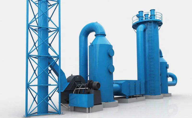
Robust Physical Structure of the Ionization Catcher
2. Deciphering the Schematic Diagram: How it Works
To truly comprehend the efficiency of the Ionization Catcher, one must examine the cross-sectional fluid dynamics and electrostatic forces occurring within the reactor tubes. The schematic diagram reveals a masterful manipulation of Coulomb forces designed to separate liquid and solid impurities from the gas stream without ever relying on restrictive mechanical filters.
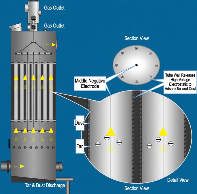
Schematic Overview: Electrostatic Ionization and Gravity Discharge Mechanics
Center Negative Electrode and Ionization
As detailed in the schematic, the core of the system relies on a perfectly centered discharge wire acting as the negative electrode. When smoke containing impurities such as tar, aerosols, and droplets passes upward through this electric field, it encounters a massive, continuous corona discharge. The high-voltage field ionizes the surrounding gas medium, generating a dense cloud of free electrons and negative gas ions.
The impurities in the gas stream—specifically the sub-micron dust and viscous tar—violently collide with these free electrons. The impurities, now adsorbed with negative ions and electrons, are aggressively propelled toward the outer precipitation electrode under the intense action of the electric field’s Coulomb force. This targeted migration prevents the particulate matter from continuing upward and escaping with the clean gas stream.
Tube Wall Adsorption and Gravity Discharge
Simultaneously, the outer tube wall functions as the grounded, positive collection surface. As the highly charged particles collide with this precipitation electrode, they immediately release their electrical charge and physically adsorb onto the tube wall. This critical interaction is scientifically defined as the charging and neutralization phenomenon.
Because the collected material consists primarily of semi-liquid tar and condensed moisture, the system possesses a natural self-cleaning ability. When the mass of the impurities adsorbed on the precipitation electrode increases to a point where gravity overcomes the surface adhesion force, the accumulated tar will automatically flow down along the smooth inner walls of the tube. This liquid waste is subsequently discharged safely from the bottom of the ionization catcher, while the purified, clean gas exits smoothly from the upper exhaust port.
3. Precision Structural Engineering: The Corona System
To safely operate within the volatile, highly humid, and deeply corrosive environments of the chemical and coking industries, the Ionization Catcher is built with specialized, high-durability internal support components. These parts are engineered to resist acidic attack and prevent catastrophic electrical shorting across the framework.
Suspension and High-Voltage Insulation
The physical engine driving the equipment’s ionization capability is the Corona System. This entire assembly is typically installed securely inside the tar removal tower. The primary structural component is the corona wire, meticulously supported and tensioned by a framework comprising high-voltage porcelain bottles, robust suspension rods, upper and lower umbrella rings, and heavy stabilizing weights. Ensuring these wires remain perfectly taut and centered is absolutely essential to maintaining a uniform electric field without sparking against the grounded tube walls.
However, in a chemical plant, extreme humidity and the presence of volatile organic compounds present a massive, constant risk of electrical grounding. If moisture is permitted to condense on the suspension structures, the high-voltage electricity will track across the wet surface, violently short-circuiting against the steel casing. To proactively prevent this, the insulator is equipped with a dedicated thermal insulation box and is fitted with a specialized electric heating device. This constant, thermostatically controlled heating guarantees that acidic mist and water droplets cannot condense on the high-voltage porcelain bottles, ensuring continuous, safe operation even when the gas stream is fully saturated.
4. Intelligent Power Supply and Process Control
Delivering raw electrical power to the corona wires is insufficient; the high voltage must be intelligently and precisely modulated to match fluctuating chemical gas loads without generating dangerous electrical arcs. Our systems are driven by advanced automation hardware to ensure maximum safety, consistent capture efficiency, and automated fail-safes.
High Voltage Control Cabinet
Functioning as the centralized brain of the operation, the High Voltage Control Cabinet manages power input, working voltage adjustment and output, operational fault alarms, and automatic cut-offs. In a chemical plant setting, where highly flammable gases or explosive dust concentrations might be intermittently present, an automated microsecond fault response is paramount. All these intricate operations are completed by robust components inside the cabinet and user-friendly knobs and buttons on the panel. The operating status is continuously displayed by precision instruments and indicator lights, allowing operators to monitor system health remotely.
High Voltage Electrostatic Silicon Rectifier
To generate the immense electrical field necessary to ionize the gas and capture sub-micron tar droplets, standard alternating grid power must be significantly transformed. The High Voltage Electrostatic Silicon Rectifier ensures that the alternating voltage output from the control cabinet is boosted and rectified into high-voltage direct current (DC). This steady DC voltage is then safely supplied to the corona electrode system, providing the highly concentrated, stable corona discharge required to capture over 95% of airborne chemical impurities without disruptive voltage ripples.
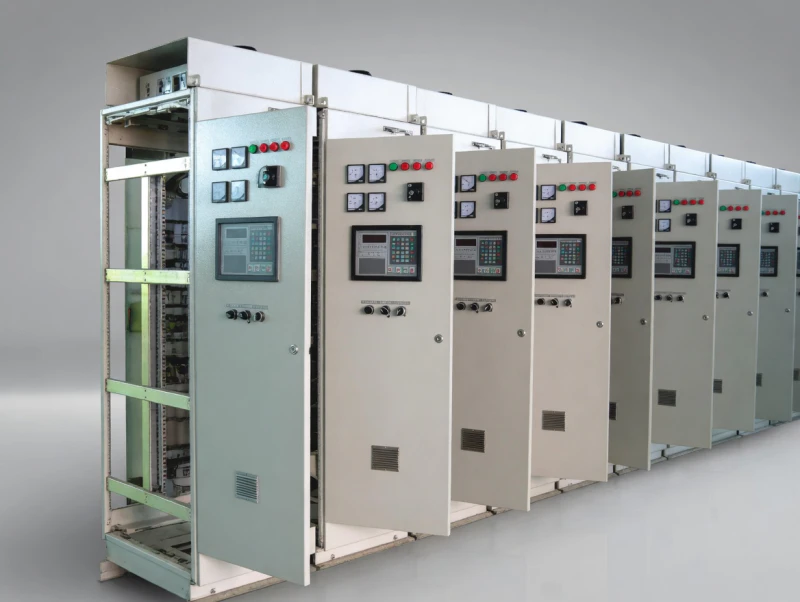
Integrated High Voltage Control Cabinet and Power Control Hardware
5. System Specifications and World-Class Manufacturing
The BLBZQ Ionization Catcher series is meticulously designed for extreme scalability and profound energy efficiency. Depending on the specific industrial chemical requirement, the standard models are engineered to handle gas volumes ranging from a moderate 10,000 cubic meters per hour up to a robust 30,000 cubic meters per hour. To easily accommodate this massive volumetric flow, the reactor chambers house between 37 and 91 precipitation electrode tubes. The tubes themselves are constructed from highly durable materials, specifically utilizing galvanized round tubes with exact dimensions of a 250mm diameter by a 4000mm length, and a sturdy wall thickness of 0.8mm.
In terms of operational expenditure, these environmental protection systems are highly optimized. Due to the streamlined aerodynamic design of the vertical tubes, the system boasts an incredibly low aerodynamic wind resistance (pressure drop) of just 300 Pascals. This prevents unnecessary strain on the facility’s induced draft fans, saving substantial electricity over the plant’s operational lifetime. Direct power consumption of the high-voltage system is also highly economical, ranging from merely 15 Kilowatts to 42 Kilowatts depending on the exact model scale.
Unrivaled Production Capacity
Such precision engineering demands immense, sophisticated manufacturing capability. Our company serves as a premier integrated supplier specializing in the research, development, and production of comprehensive environmental protection system equipment, boasting an annual production capacity that exceeds 50,000 tons. To ensure flawless construction and prompt delivery, our facilities are equipped with specialized production lines for polar plates and discharge electrodes of dust removal equipment.
Additionally, we utilize large-scale edge planers and plate bending machines specifically for manufacturing massive ring girders. These state-of-the-art facilities fully meet the demanding requirements of mass production. Adhering strictly to the ISO9001 management system, our production quality confidently maintains a leading position in the industry. Advanced fabrication tools, including CNC cutting machines, robotic automatic welding stations, and laser engraving machines, guarantee that every Ionization Catcher delivered to the field operates flawlessly under the harshest chemical environments.
Recover Value and Ensure Strict Compliance
For the chemical, coking, and carbon industries, treating viscous tar and volatile droplets is no longer just a matter of meeting basic environmental regulations—it is a strategic opportunity to actively recover valuable chemical byproducts and aggressively protect your downstream exhaust equipment from catastrophic, sticky failures. Do not allow tar to blind your filters and halt your production lines. Contact our expert environmental engineering team today to architect an Ionization Catcher system strictly custom-tailored to your exact chemical exhaust profile.


