Regenerative Catalytic Oxidation (RCO)
Perfectly blending the 95%+ heat recovery efficiency of an RTO with the low-temperature catalytic technology of a CO system. Achieve up to 99% VOC destruction efficiency with the absolute lowest operating energy consumption.
Contact UsIntroduction to RCO Process
The Regenerative Catalytic Oxidation (RCO) technology heats organic waste gas to above 300°C. Under the action of a catalyst in the combustion chamber, Volatile Organic Compounds (VOCs) are oxidized and decomposed into harmless CO₂ and H₂O, achieving a purification efficiency of up to 99%.
The high-temperature gas generated flows through specially designed ceramic regenerators and catalysts, heating the ceramic body to "store heat". In the subsequent cycle, incoming waste gas passes through this heated ceramic, transferring the stored heat to the exhaust.
By utilizing the ceramic as a heat exchange medium in a continuous cycle, the system significantly reduces the fuel consumption required to heat the waste gas, lowering operating costs and achieving a remarkable heat recovery efficiency of up to 95%.
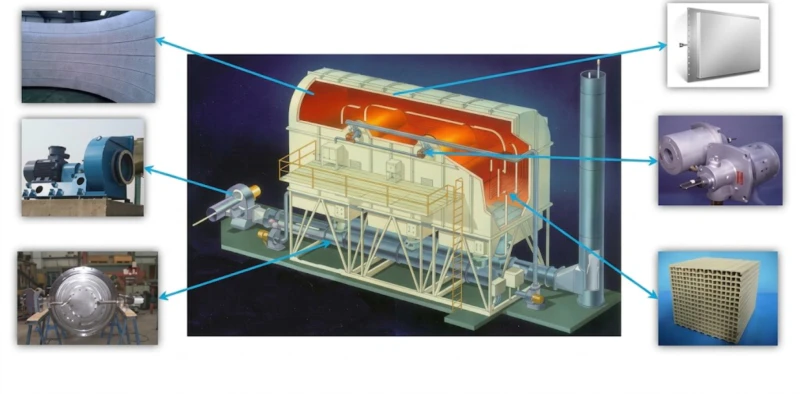
System Components
Key System Components
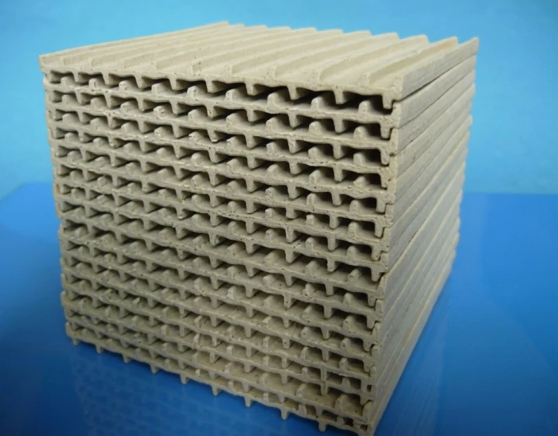
Regenerative Body

Thermal Insulation Cotton
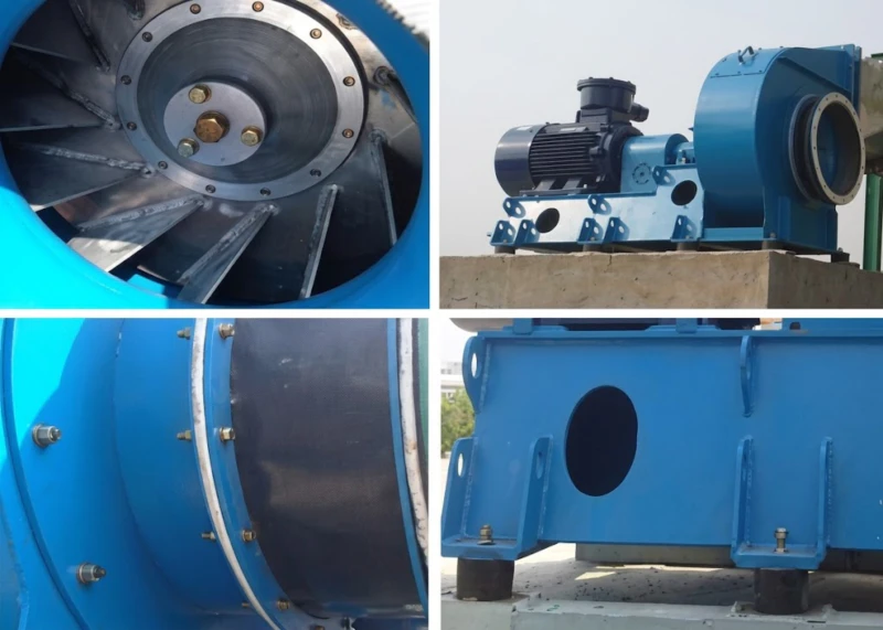
Fan System
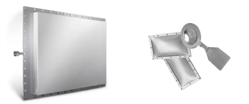
Rupture Disc

Valve System

Catalyst
How RCO Works
Preheating
VOCs gas enters the first regenerative chamber via switching valves. The gas absorbs thermal energy from the preheated ceramic media, rapidly rising to the catalyst activation temperature.
Catalytic Oxidation
The heated gas passes through the catalyst bed. VOCs are oxidized into harmless CO₂ and H₂O at low temperatures (250°C-400°C), simultaneously releasing reaction heat.
Heat Recovery
High-temperature purified gas flows through the second regenerative chamber. It transfers its heat back to the ceramic media (storing heat for the next cycle) while cooling down.
Purified Emission
The cooled, clean gas is safely discharged through the chimney. PLC systems periodically switch the valve direction to maintain a continuous, highly energy-efficient cycle.
Key Features & Benefits
Discover why Regenerative Catalytic Oxidation is the most energy-efficient solution for treating large volumes of VOCs.
Ultimate Cost Efficiency
Combining exceptional heat recovery (>95%) with low reaction temperatures enables "self-sustaining" operation without any additional fuel consumption, even when treating extremely low-concentration VOCs.
Extended Equipment Lifespan
By lowering the combustion chamber temperature from 800°C (standard RTO) to below 400°C, the system drastically reduces thermal stress and fatigue on metal components and minimizes insulation degradation.
Zero NOx Emissions
Low-temperature catalytic oxidation fundamentally prevents the formation of thermal nitrogen oxides (NOx) typically associated with high-temperature combustion, eliminating secondary pollution.
Exceptional Safety Profile
The system operates at temperatures significantly lower than the auto-ignition points of most organic compounds, ensuring the highest level of operational safety for your facility.
Golden Triangle Selection
Understand the core differences between CO, RTO, and RCO to choose the perfect emission control system for your facility.
| Comparison Dimension | CO (Catalytic Oxidation) |
RTO (Regenerative Thermal Oxidation) |
Energy Saver
RCO (Regenerative Catalytic Oxidation) |
|---|---|---|---|
| Heat Recovery Method | Plate Heat Exchanger (Efficiency: 50%-70%) |
Ceramic Honeycomb (Efficiency: >95%) |
Ceramic Honeycomb (Efficiency: >95%) |
| Operating Temperature | 250°C - 350°C | 800°C - 850°C | 300°C - 400°C |
| Suitable Air Volume | Small to Medium | Medium to Ultra-Large | Large to Ultra-Large |
| VOC Concentration | Medium to High | Medium to Low | Extremely Low to Medium-Low |
| Gas Composition Limits | Extremely Strict (High risk of poisoning) |
Broad / Highly Tolerant (Handles complex impurities) |
Strict (Requires anti-poisoning & dust filtering) |
The Expert Conclusion
If you are dealing with large air volumes and extremely low VOC concentrations without severe catalyst poisons, RCO is undeniably your top choice. It perfectly marries the massive heat recovery of an RTO with the low-temp fuel savings of a CO system.
Ideal Applications & Scenarios
Crucial Engineering Prerequisite
RCO systems are the ultimate energy savers for large air volumes with low VOC concentrations. However, the exhaust gas must be strictly free of heavy particulate matter and catalyst-poisoning substances. Environments containing Sulfur, Phosphorus, Halogens, or Heavy Metals will deactivate the catalyst and are highly discouraged without extensive pre-treatment.
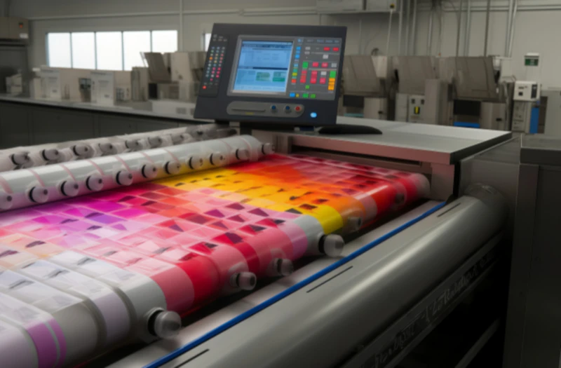
Printing & Packaging
Highly effective for large printing and packaging facilities, including flexographic and rotogravure printing processes, efficiently breaking down ink solvents and ensuring clean emissions with minimal fuel overhead.
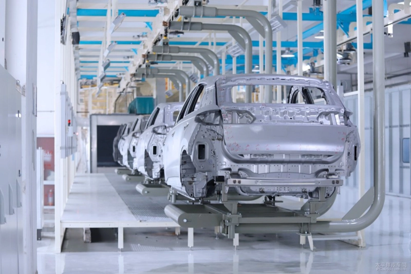
Automotive Spray Painting
Perfect for automotive manufacturing, auto parts spray booths, and large-scale metal finishing. These processes typically generate massive exhaust air volumes with very low VOC concentrations, making RCO the most economical choice.
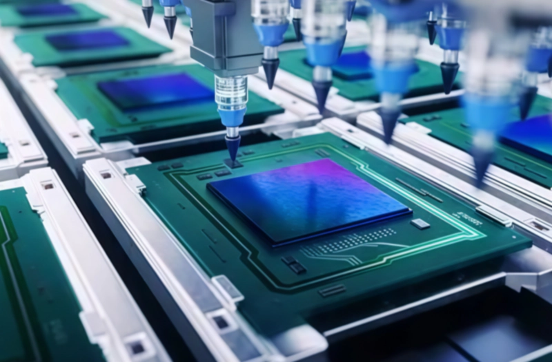
Electronic Semiconductors
Ideal for safely oxidizing specific solvents, cleaning agents, and VOCs generated during semiconductor fabrication, printed circuit board (PCB) manufacturing, and precision electronics coating processes.
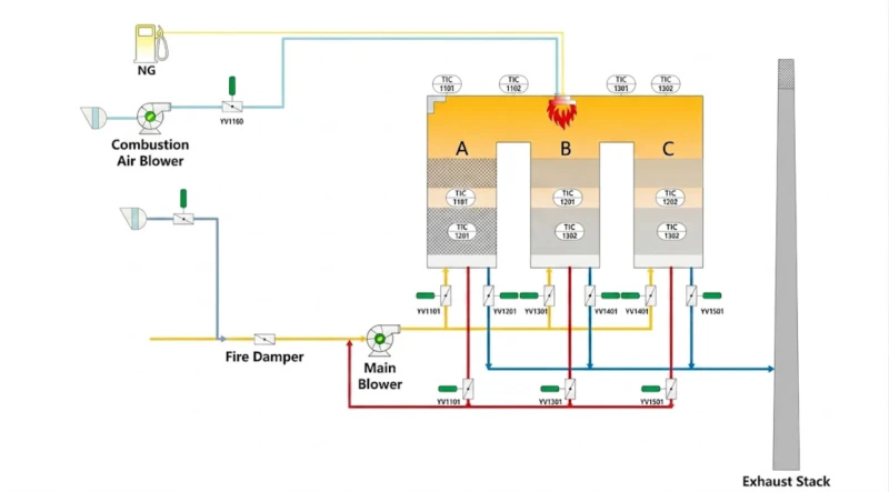
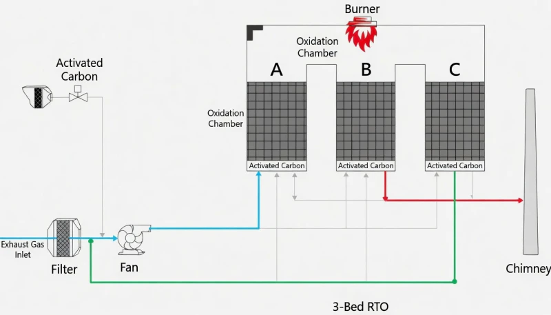
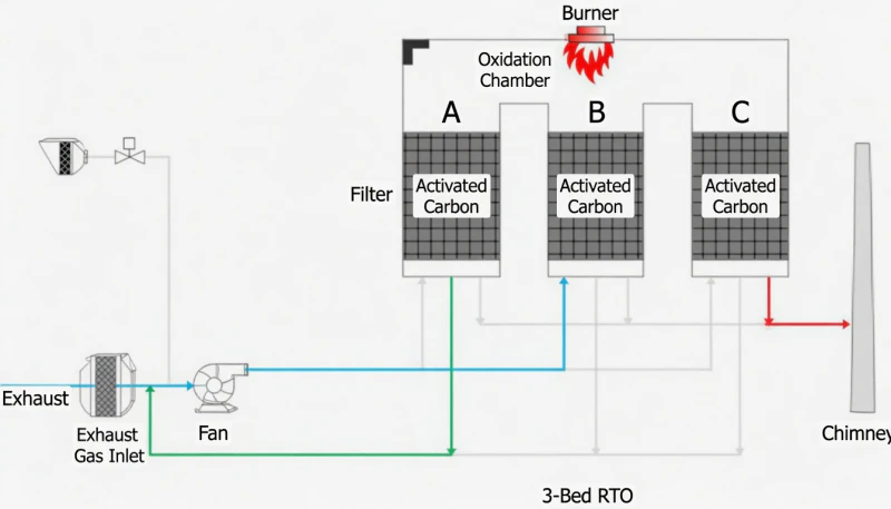
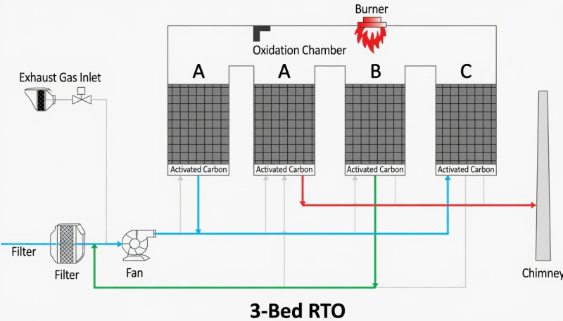
RCO Switching Sequence
A continuous 3-bed operating cycle ensures uninterrupted VOC destruction, prevents pressure spikes, and guarantees maximum heat recovery through systematic inlet, outlet, and purge phases.
Trusted by Industry Leaders
Hear from clients who have achieved absolute environmental compliance and significant energy savings using our advanced Catalytic Oxidation systems.
The RCO system installed slashed our operating energy costs by nearly 70% while maintaining absolute VOC compliance. The ROI has been phenomenal.
Their engineering expertise was critical in managing our complex, large-volume exhaust stream. The installation was seamless, and the performance exceeds expectations.
Professional, responsive, and truly experts in VOC abatement. The catalytic system achieves 99%+ efficiency consistently. We highly recommend them.


