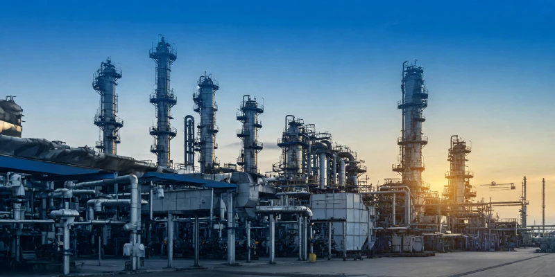
In the modern era of environmental stewardship, industrial emission control has shifted from simple filtration to advanced molecular and aerosol management. The Ionization Catcher stands as a pinnacle of innovation in environmental protection and energy recovery[cite: 10, 12]. These systems are not merely filters but integrated engineering marvels that encompass design, manufacturing, installation, and commissioning into a single turnkey solution[cite: 11]. Primarily serving the chemical, coking, carbon, spraying, and printing industries, the Ionization Catcher series achieve highly efficient treatment of viscous tar and multi-phase particulate matter that would render traditional systems obsolete[cite: 10, 14].
Industrial Deployment of High-Efficiency Ionization Catchers
1. Why Traditional Systems Fail Against Viscous Contaminants
The central challenge in modern exhaust management is the presence of viscous liquid aerosols. In industries like spray painting, high-speed printing, and chemical coking, the exhaust gas is not a dry stream of dust. Instead, it is a volatile, multi-phase mixture of semi-liquid tar droplets, resin mists, curing agents, and moisture-saturated aerosols. When these contaminants are introduced to a standard fabric filter, they exhibit a phenomenon known as “capillary binding.” The sticky liquids are drawn into the microscopic fibers of the filter media, where they react and harden into an impermeable crust. This “bag blinding” is permanent and results in a sudden, catastrophic spike in pressure drop, rendering the entire system useless.
Similarly, traditional dry electrostatic precipitators struggle with these fluids. Because the contaminants are sticky, they do not fall away from the collection plates when rapped by mechanical hammers. Instead, they smear and accumulate, forming massive bridges of solidified waste that span the gap between high-voltage electrodes and grounded plates. This creates a direct electrical path, leading to constant short-circuiting, dangerous arcing, and a total loss of capture efficiency. To operate reliably, industrial facilities require a system designed specifically to handle these fluids through electro-physical manipulation rather than physical interception.
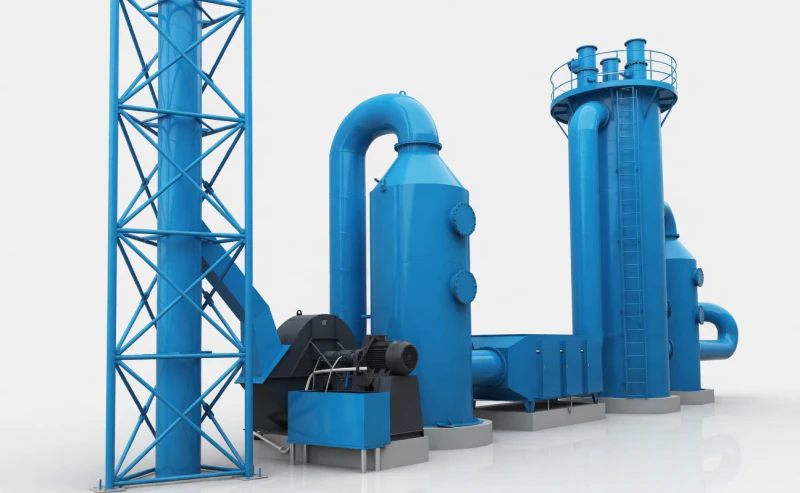
Heavy Industrial Structural Integrity of the Ionization Catcher
2. Decoding the Internal Mechanics and Schematic
The Ionization Catcher operates on the principle of the electric field’s Coulomb force to achieve separation. By transforming the physical behavior of impurities through high-voltage ionization, the system achieves near-zero emission standards without the maintenance burden of dry filters[cite: 23, 24].
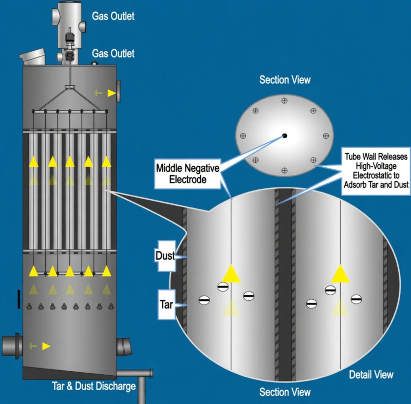
Structural Schematic: Electrostatic Ionization and Gravity Separation
Ionization and the Center Negative Electrode
As shown in the technical schematic, the reactor core features a central discharge wire acting as the negative electrode. When smoke containing tar and mist impurities enters this zone, it is subjected to an intense high-voltage field[cite: 23]. This corona wire produces a dense cloud of negative ions and electrons that saturate the gas stream[cite: 50].
The suspended impurities—dust and tar aerosols—adsorb these negative ions and electrons, effectively gaining a powerful negative charge[cite: 24, 50]. This process, known as the “charging phenomenon,” prepares the particles for the final capture stage. Driven by the Coulomb force, these charged particles are violently propelled away from the central electrode toward the outer collection surface[cite: 24].
Wall Adsorption and Gravity Self-Cleaning
The outer tube wall serves as the grounded precipitation electrode. Upon impact, the charged tar and dust release their charge and adsorb onto the wall surface[cite: 24]. Unlike solid dust systems, the liquid nature of these contaminants allows the system to clean itself. As the mass of adsorbed impurities increases, gravity overcomes the surface adhesion force[cite: 25].
This results in a continuous, automatic downward flow of liquid waste. The semi-liquid tar and slurry are discharged from the equipment bottom, while the purified, clean gas exits securely from the top[cite: 25]. This gravity-driven mechanism ensures the reactor tubes remain clear, maintaining a remarkably low wind resistance of 300 Pa and minimizing energy waste[cite: 60].
3. High-Voltage Automation and Control Excellence
The high-performance ionization field requires sophisticated electrical management. Standard grid power is insufficient; it must be intelligently rectified and monitored to respond to fluctuating gas volumes and chemical concentrations without causing dangerous arcing[cite: 52, 54, 55].
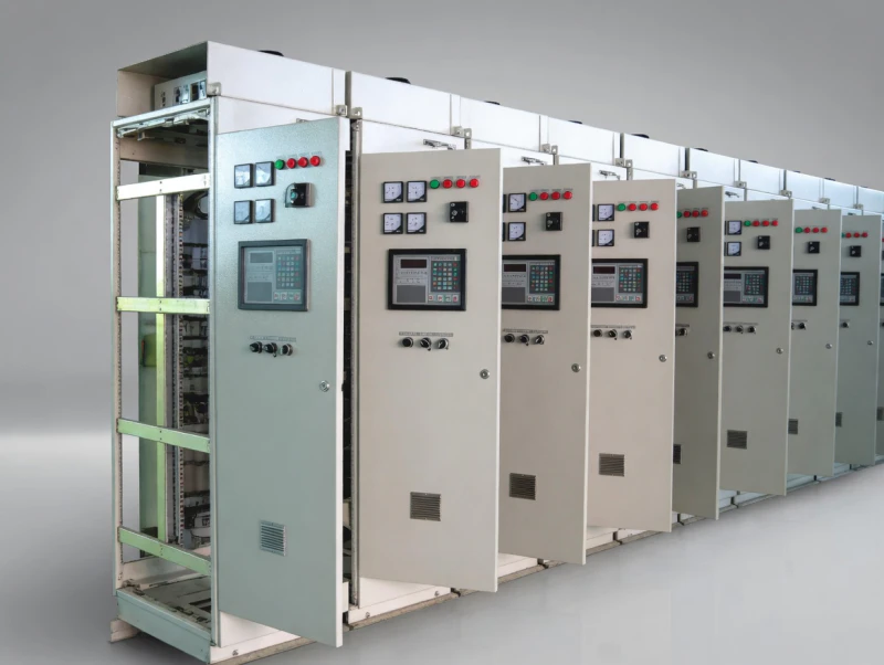
The Intelligent Control Ecosystem
The brain of the system is the High Voltage Control Cabinet. It meticulously manages power input, working voltage adjustment, and output distribution[cite: 31, 52]. In the volatile environments of chemical plants or spraying booths, safety is paramount. The control center features integrated operational fault alarms and an automatic cut-off mechanism that triggers in milliseconds if a discharge instability is detected[cite: 52]. Plant operators can monitor the system in real-time through precision instruments and status indicator lights on the front panel[cite: 31, 53].
To generate the necessary electrical field strength, the system utilizes a High Voltage Electrostatic Silicon Rectifier. This hardware transforms the alternating voltage from the cabinet, boosting and rectifying it into a stable, high-voltage direct current (DC) supplied to the corona electrode system[cite: 33, 55]. This specialized rectification ensures that sub-micron tar droplets are captured with over 95% efficiency while preventing the voltage ripples that could trigger hazardous electrical fires in chemical processing environments.
High Voltage Automation Control and Silicon Rectifier Unit
4. Technical Specifications and Selection Matrix
Proper integration depends on matching equipment scale with the specific volumetric and chemical profile of the plant. The BLBZQ series is designed for extreme scalability, handling gas volumes from 10,000 cubic meters per hour to 30,000 cubic meters per hour in standalone configurations[cite: 58, 60].
| Model Number | Air Volume (m3/h) | Electrode Tube Count | Energy Drain (KW) |
|---|---|---|---|
| BLBZQ-10000 | 10,000 | 37 Tubes | 15 KW |
| BLBZQ-20000 | 20,000 | 73 Tubes | 29 KW |
| BLBZQ-30000 | 30,000 | 91 Tubes | 42 KW |
The precipitation electrode tubes are crafted from galvanized circular tubes measuring 250mm in diameter and 4000mm in length, with a sturdy wall thickness of 0.8mm[cite: 60]. This structural rigidity is crucial for the corona system, which includes high-voltage porcelain bottles, suspension rods, upper and lower umbrella rings, and heavy weights designed to maintain perfectly vertical alignment[cite: 49]. Furthermore, to handle the extreme moisture of chemical plants, insulator boxes are equipped with internal heating devices and thermal insulation to prevent acid dew-point tracking and electrical failure[cite: 35, 57].
5. Unrivaled Production Capacity and Quality Control
Supporting massive multi-sector scenarios requires colossal manufacturing prowess. As a premier integrated supplier, our annual production capacity exceeds 50,000 tons[cite: 63, 64]. We possess dedicated high-tech production lines for the fabrication of polar plates and discharge electrodes[cite: 64]. Our factory is equipped with large-scale edge planers and plate bending machines designed specifically for manufacturing the heavy ring girders required by industrial-scale ionization catchers[cite: 64].
CNC Precision
State-of-the-art CNC cutting machines ensure that every component matches technical schematics with millimetric precision, eliminating the mechanical instability that causes electrical sparking[cite: 66, 67].
Robot Automation
Utilizing robotic automatic welding stations guarantees structural welds with maximum integrity, vital for the high-pressure and corrosive environments of chemical tar removal towers[cite: 68, 70].
ISO9001 Standards
Our manufacturing operations strictly adhere to the international ISO9001 management system, maintaining a leading position in the industry for production quality and reliability[cite: 65].
By leveraging this advanced manufacturing infrastructure, our specialized departments—covering VOCs, Desulfurization, De-NOx, and Carbon Neutrality—can provide integrated supply for complex engineering projects[cite: 84, 85]. Whether it is treating paint mist in a furniture kiln or heavy tar in a coking facility, our systems achieve the stability and efficiency required by global environmental regulations[cite: 10, 13, 14].
Secure Your Facility with Internationally Leading Technology
Sticky tar aerosols, ink mists, and viscous overspray are the silent killers of industrial filtration efficiency. Do not settle for standard dry systems that are destined for failure. Contact our environmental engineering team today to architect an Ionization Catcher system custom-tailored to your exact multi-phase contaminant profile. Ensure safe, compliant, and highly energy-efficient operation for your plant.


