Case Study · VOC Abatement
How a specialist high-tech enterprise producing organofluorine chemicals and polyacrylate products achieved 97.6% VOC removal and NMHC outlet below 15 mg/Nm³ from 20,000 Nm³/h of complex multi-source fine chemical off-gas — using alkali wash and water wash pre-treatment to address acid gases and water-soluble organics, then RCO (Regenerative Catalytic Oxidizer) rather than RTO for the final oxidation step, enabling >95% VOC destruction at >300°C with an explosion-proof zone installation that RTO’s open-flame combustion chemistry makes impossible.
RCO Catalytic Oxidation
Explosion-Proof Zone
Organofluorine Production
300°C Low-Temperature Oxidation
01 — Industry Background and the RCO vs RTO Decision
Fine Chemical Multi-Product Production: Three Specific Reasons Why RCO Replaces RTO in This Application
Fine chemicals are a high-technology-intensive sector encompassing pharmaceuticals, agrochemicals, dye intermediates, food additives, and performance materials. Production is characterised by multi-step synthesis routes, diverse solvent usage, and small production quantities with high product value. The enterprise in this case study is a provincial high-technology enterprise with annual production capacity of 90,000 t of organofluorine chemical products and 250,000 t of polyacrylate polymer products, with an established organofluorine production base, polymerisation acrylate production base, and lithium battery material production base. Its organofluorine products (including organofluorine agricultural chemicals, pharmaceutical intermediates, and fluorinated monomers) and polyacrylate products (dispersion adhesives, emulsion polymers) serve specialty materials markets with significant regulatory-driven growth.
The decisive technology selection in this project is the choice of RCO (Regenerative Catalytic Oxidizer) over RTO (Regenerative Thermal Oxidizer). The experience summary explicitly documents the three reasons:
Why RCO Instead of RTO: Three Documented Reasons
- 1
Production area classified as explosion-proof zone — RTO cannot be installed. The organofluorine production workshops and tank farms operate in areas classified as ATEX explosion-proof zones (due to flammable solvent vapour in the ambient air). RTO technology uses open-flame combustion (≥760°C burner) to oxidise VOCs. Installing open-flame combustion equipment in or adjacent to an explosion-proof zone violates both ATEX Directive 2014/34/EU and IEC 60079 zone classification requirements. RCO uses catalytic oxidation at >300°C without open flame; the catalytic reaction is flameless, making RCO installation in or near explosion-proof zones compliant with zone classification requirements. - 2
Gas concentration is moderate with some fluctuation — RCO operates at lower temperature, saving energy versus RTO. At 500 mg/Nm³ NMHC, the fine chemical off-gas in this installation is below the autothermal threshold for RTO (≈2,500–3,000 mg/Nm³). A direct RTO would require continuous supplementary natural gas to maintain 760°C, creating significant ongoing fuel cost. RCO requires only approximately 300°C catalyst temperature — achievable with the electrical heater (400 kW installed) and the catalytic exothermic heat at moderate VOC concentration. The energy cost to reach and maintain 300°C is far lower than to maintain 760°C, particularly when the VOC concentration is insufficient for autothermal RTO operation. - 3
RCO raises the high-temperature heat storage efficiency, reducing facility operating energy. The regenerative heat storage beds in RCO recover ≥95% of the catalytic reaction heat (which, though lower in absolute temperature than RTO, is still significant). By recovering this heat to pre-heat incoming raw gas, the RCO reduces the electrical heater energy input needed to maintain catalyst operating temperature during steady-state production. This heat recovery efficiency gain, applied to the lower-temperature RCO system, provides better overall energy economics than an RTO at this VOC concentration level.
02 — Pollution Profile
Fine Chemical Multi-Source Off-Gas: 500 mg/Nm³ NMHC, Acid Gases, Multiple Solvent Species, and Explosion-Proof Zone Classification
The off-gas originates from multiple sources simultaneously: vacuum pump exhaust from organofluorine reactor workshops, reactor waste gas, tank area breathing emissions, workshop and tank area off-gas, and wastewater treatment plant off-gas. All streams are combined at a common collection manifold and treated as a combined gas flow. Standard gas volume: 20,000 Nm³/h; process volume: 22,196 Nm³/h at 30°C. Fan power: 55 kW; fan pressure: 5,000 Pa; duct diameter: φ700 mm. O₂ content: 21% actual/baseline. Humidity: 40%.
The VOC profile reflects the diversity of fine chemical synthesis routes: cyclohexane, acetone, esters, polyols, and multiple other solvent species. No benzene-series aromatics (benzene, toluene, xylene) are listed as primary species in the initial gas, though the outlet limits specify benzene, toluene, and xylene limits, suggesting trace amounts are present from process chemistry side reactions. Total NMHC is 500 mg/Nm³ — moderate concentration, below the RTO autothermal threshold but suitable for RCO catalytic oxidation. The wastewater treatment plant off-gas component contains sulfide chlorides and other acidic species that require alkali wash pre-treatment before the RCO.
Explosion-proof zone classification is the critical site constraint: the organofluorine production area and associated tank farm are classified as explosion-proof zones under EU ATEX Directive 2014/34/EU. This classification prohibits open-flame combustion equipment (including RTO natural gas burners, which operate at ≥760°C with a pilot flame) in these zones or in directly adjacent locations without specific safety engineering review. The RCO’s flameless catalytic oxidation mechanism (electrical heater brings catalyst to >300°C; oxidation proceeds catalytically without flame) is compatible with explosion-proof zone proximity, making it the only viable thermal oxidation technology for this installation.
| Parameter | Initial Concentration | Actual Outlet | EU IED / NER Limit |
|---|---|---|---|
| NMHC (total VOCs) | 500 mg/Nm³ | 12 mg/Nm³ (<15 online) | IED ≤40 mg/Nm³ |
| Benzene | Trace (process chemistry) | 0.5 mg/Nm³ | IED ≤2 mg/Nm³ |
| Toluene | Trace | 3 mg/Nm³ | IED ≤5 mg/Nm³ |
| Xylene | Trace | 4 mg/Nm³ | IED ≤8 mg/Nm³ |
| Acid gases (from wastewater off-gas) | Sulfide chlorides present | Removed by alkali wash | — |
| Standard gas volume | 20,000 Nm³/h | — | — |
| Process gas volume | 22,196 Nm³/h at 30°C | — | — |
| Site zone classification | Explosion-proof zone (ATEX) | — | ATEX 2014/34/EU |
| Annual VOC reduction | ~345 t/year | Verified | — |
03 — RCO Technology Explained
How Regenerative Catalytic Oxidation (RCO) Achieves >95% VOC Destruction at >300°C Without Open Flame
Regenerative Catalytic Oxidation (RCO) uses a catalyst to lower the activation energy of the organic compound oxidation reaction, enabling complete destruction at temperatures of 260–400°C rather than the 760°C–850°C required for thermal (non-catalytic) oxidation. The oxidation chemistry is the same as in RTO:
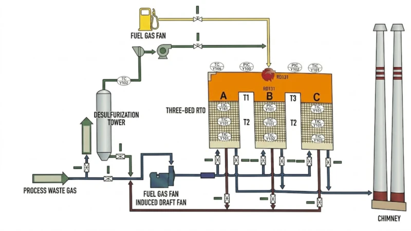
The catalyst provides an alternative reaction pathway with lower activation energy, allowing the reaction to proceed at 300°C rather than 760°C. The RCO system structure mirrors the three-bed RTO layout, using the same ceramic heat storage regenerative principle to recover ≥95% of the reaction heat and pre-heat incoming raw gas. The difference is that the combustion chamber of the RTO is replaced by a catalyst bed in the RCO, and the combustion temperature is replaced by the catalyst activation temperature.
The gas flow through the RCO is as follows: gas passes through the pre-heated ceramic regenerative heat storage bed, rising from ambient to approximately 300°C; the pre-heated gas contacts the catalyst, where the VOC oxidation reaction proceeds catalytically at the catalyst surface; the hot oxidation products (CO₂, H₂O, heat) exit the catalyst bed and pass through the second ceramic heat storage bed, transferring their heat to pre-heat the next cycle of incoming gas. The electrical heater (400 kW installed; 150 kW startup; 420 kW cold start) provides initial heating to bring the system to catalyst operating temperature, after which the exothermic catalytic reaction maintains the temperature without external energy input (at sufficient VOC concentration).
RCO vs RTO Comparison at a Glance
| Feature | RTO | RCO (This Project) |
|---|---|---|
| Oxidation mechanism | Thermal (open flame) | Catalytic (flameless) |
| Operating temperature | 760–850°C | >300°C |
| Explosion-proof zone suitability | Not suitable (open flame) | Suitable (flameless) |
| Energy at low VOC concentration | High (must heat to 760°C) | Lower (only 300°C) |
| Thermal recovery efficiency | ≥95% | ≥95% |
| VOC removal efficiency | ≥99% | ≥95% |
| Catalyst service life / cost | N/A (no catalyst) | 3–5 year catalyst replacement cost |
| Halogenated VOC tolerance | Tolerant (with HX/scrubber) | Sensitive (poisons catalyst) |
| Autothermal threshold | ≈2,500–3,000 mg/Nm³ | Lower (≈800–1,200 mg/Nm³) |
04 — Treatment Solution
Alkali Wash + Water Wash + RCO: Pre-Treatment Protects the Catalyst; RCO Enables Flameless Explosion-Safe Oxidation
The three-stage process chain mirrors the pharmaceutical RTO application (Case 22) in its pre-treatment philosophy, but substitutes the RCO for the RTO in the final oxidation stage. The pre-treatment stages protect the RCO catalyst from the acid gas components and water-soluble organics that would damage or deactivate the catalyst surface. The RCO then provides the >95% VOC destruction at >300°C without the open flame that the explosion-proof zone classification prohibits.
Stage 1: Alkali Wash (Acid Gas Removal)
Gas from all collection sources enters the alkali wash stage. The wastewater treatment plant off-gas contains sulfide chlorides and acidic species from biological treatment. These acid gas components would, if reaching the RCO catalyst, poison the catalyst surface by occupying active sites with sulfur or chlorine compounds. The alkali wash removes these components by absorption in NaOH solution, protecting the catalyst. The alkali wash is also the first-line pre-treatment for any acid gases generated in the organofluorine workshop processes.
Stage 2: Water Wash (Water-Soluble Organic and Moisture Management)
Post-alkali-wash gas enters the water wash stage for further removal of water-soluble organic compounds and moisture management. High humidity in the combined gas (40%) can reduce RCO catalyst activity by competing with VOC adsorption on catalyst active sites and by promoting hydrolysis reactions that degrade catalyst surface chemistry. The water wash, combined with temperature adjustment before the RCO inlet (≤40°C inlet requirement), ensures the gas enters the catalyst bed at the correct temperature and humidity.
The combined gas from all sources (fan, tank area, workshop, wastewater) is collected through a manifold combining fan and ventilation room gas, tank area and building off-gas to a common gas collection header. Due to the wastewater off-gas containing acid groups (sulfide chlorides), it is pre-treated through alkali wash and water wash. Under fan driving, the gas rapidly fills the inlet circuit, then is cut in the bottom-entry top-exit direction into the scrubber zone. At the packing surface, gaseous components separate from the NaOH liquid, acidic gas is adsorbed by the alkaline scrubbing liquid and flows downward to the liquid tank. On the spray section above the packing, the gas rises uniformly and enters one spray layer of spray material. At the spray section the gas and liquid are uniformly distributed and intimately contacted through the spray zone process; the absorber handles residual spray fogs. The gas rises to the upper spray section then enters a mist eliminator. Through the action of the mist eliminator and gravity, the spray fog formed in the spray section is removed, and the separated water flows downward along the inner wall of the absorber to the slurry storage tank. Gas passes from the second cooling mist eliminator with different spray densities. The spray pressure is different in the two sections, the spray concentration covers the full spray range there, and the liquid absorptive gas can be kept stable in this way. Through controlled air flow and fill time within this process, the gas here is removed and settled, to be finally re-entered into the RCO heating combustion system. The treated concentration after water wash is relatively stable, and the gas can reach emission levels.
Stage 3: RCO (Regenerative Catalytic Oxidizer, >300°C)
The pre-cleaned gas enters the RCO. The electrical heater brings the system to the catalyst operating temperature (>300°C) during startup. During steady-state production at 500 mg/Nm³ NMHC, the exothermic catalytic oxidation provides the heat input to maintain the catalyst temperature, reducing or eliminating the electrical heater load. Key RCO parameters: processing flow 20,000 m³/h; inlet temperature ≤40°C; processing efficiency >95%; thermal efficiency >95%; catalyst temperature >300°C; catalyst volume 3.1 m³; combustor rating 2,100,000 kcal/h; electrical heater power 400 kW; startup energy 150 kW·h; cold start energy 420 kW·h; system pressure drop <3,000 Pa; equipment weight 80 t; footprint 30×7 m.
Vacuum + Tank
WW off-gas
H₂S + Acid
Gas removal
H₂O-soluble
Humidity ↓
>300°C
Flameless
12 mg VOC
97.6%
⭐ RCO uses flameless catalytic oxidation — suitable for explosion-proof zones where open-flame RTO is prohibited.
Equipment Specification
| Item | Specification |
|---|---|
| RCO processing flow | 20,000 m³/h; ≤40°C inlet; >300°C catalyst; footprint 30×7 m; 80 t |
| Processing / thermal efficiency | >95% / ≥95% |
| Catalyst volume | 3.1 m³ (two-bed configuration) |
| Combustor rating | 2,100,000 kcal/h |
| Electrical heater | 400 kW installed; 150 kW startup; 420 kW cold start |
| RCO fan | 45 kW |
| Total electrical power | 445 kW installed (380 V, 50 Hz, 3-phase) |
| Compressed air | 25 m³/h (P: 0.6–0.8 MPa) |
| Annual electricity cost | 36 kW·h/h consumption; 29 RMB/h; 8,000 h/year = approx. 232,000 RMB/year |
| Annual compressed air cost | 60 m³/h; 12 RMB/h; 8,000 h = approx. 96,000 RMB/year |
| Total annual operating cost | 328,000 RMB/year (328,000 RMB/year) |
.webp)
05 — Core Advantages
Five Reasons Why RCO Is the Right Choice for Fine Chemical Explosion-Proof Zone VOC Applications
- ✓
Flameless Catalytic Oxidation Is the Only Viable Open-System Thermal Treatment for Explosion-Proof Zones: ATEX Directive 2014/34/EU requires all equipment in explosion-proof zones to be designed and certified to prevent ignition of explosive atmospheres. RTO burners operating at ≥760°C with a continuous pilot flame are inherently incapable of meeting ATEX equipment certification for Zone 1 or Zone 2 hazardous areas. RCO’s electrical heater (which can be specified to ATEX Ex-d or Ex-e classification) and catalytic bed (which has no internal ignition sources) can be designed to comply with ATEX requirements for Zone 2 installation. For any fine chemical facility where the VOC treatment system must be sited within or adjacent to classified hazardous zones, RCO is the only regenerative thermal oxidation technology option. - ✓
Lower Operating Temperature (300°C vs 760°C) Significantly Reduces Startup Energy and Steady-State Heat Loss: The RCO electrical heater needs to raise the ceramic beds and catalyst to only 300°C during startup, versus the 760°C combustion chamber temperature of an RTO. At 300°C, the heat loss from the system to the environment is significantly lower than at 760°C (heat loss scales with temperature difference to ambient), reducing the steady-state energy input needed to compensate for these losses. This makes the RCO particularly economical during partial-load periods when VOC concentration is insufficient to fully sustain the catalyst temperature through exothermic reaction heat alone. - ✓
The Pre-RCO Alkali and Water Wash Stages Protect the Catalyst From Poisoning and Maintain Long Service Life: The RCO catalyst (typically precious metal or metal oxide supported on a ceramic carrier) is sensitive to deactivation by sulfur compounds, chloride compounds, and high-boiling organic contaminants that deposit on the catalyst surface and block active sites. The alkali wash removes sulfide and acidic chloride gases from the wastewater treatment plant off-gas before they reach the catalyst; the water wash removes water-soluble organics. Together, these pre-treatment stages ensure the gas entering the RCO catalyst is relatively clean and dry, extending catalyst service life from the 1–2 years typical without pre-treatment to 3–5 years with adequate pre-treatment. - ✓
At 500 mg/Nm³ NMHC, the RCO Autothermal Threshold Is Achievable at 300°C — No External Fuel Required at Normal Production Load: The autothermal threshold for RCO (the minimum VOC concentration at which the catalytic exothermic heat release is sufficient to maintain the catalyst temperature without external electrical heater input) is approximately 800–1,200 mg/Nm³ for typical fine chemical solvent mixtures at 300°C. At the 500 mg/Nm³ inlet concentration in this installation, the system operates near or at the autothermal boundary: the electrical heater provides some top-up to maintain the catalyst temperature. The actual electricity consumption is 36 kW·h/h — significantly less than the 400 kW full-load heater capacity, confirming that the catalytic exothermic reaction is contributing substantially to temperature maintenance. Compared with an RTO requiring constant supplementary fuel at this VOC concentration, the RCO energy economics are substantially better. - ✓
97.6% VOC Removal From a Complex Multi-Source Multi-Component Fine Chemical Off-Gas Demonstrates RCO Effectiveness Across Diverse Solvent Profiles: The 500 mg/Nm³ inlet with 12 mg/Nm³ outlet (97.6% removal) involves a highly diverse VOC mixture: cyclohexane, acetone, esters, polyols, and multiple other species from different synthesis routes in the same production facility. Each of these compounds has different catalytic oxidation kinetics and different adsorption behaviour on the catalyst surface. Achieving >95% overall removal efficiency across this entire mixture at 300°C confirms that the catalyst formulation is appropriately selected for the specific VOC profile of this fine chemical application.
06 — Operational Results
Verified Performance: NMHC <15 mg/Nm³ Online, Grade B Enterprise Status, 345 t/yr VOC Reduction
After commissioning, online VOC monitoring data consistently reads below 15 mg/m³, satisfying the applicable local permit requirement of 60 mg/m³. The facility has achieved Grade B enterprise emission classification. Annual operating cost at 8,000 operating hours: electricity at 29 RMB/h (36 kW·h/h at 0.8 RMB/kWh) = approximately 232,000 RMB; compressed air at 12 RMB/h (60 m³/h at 0.2 RMB/m³) = approximately 96,000 RMB; total approximately 328,000 RMB/year (328,000 RMB).
07 — Implementation Cautions
Critical Engineering and Operational Lessons for Fine Chemical RCO Applications
- 🚫
Catalyst poisoning is irreversible — the alkali wash and water wash pre-treatment stages must be properly maintained at all times: If sulfide or chloride compounds from the wastewater off-gas reach the RCO catalyst in significant quantities, they occupy active sites permanently, reducing catalyst activity in a way that cannot be reversed by regeneration. Once the catalyst is poisoned, it must be replaced — at significant cost and with extended downtime. The pre-treatment wash stages must be maintained as safety-critical equipment for the RCO catalyst, not merely as emission reduction stages. Monitor alkali wash outlet pH continuously and verify NaOH concentration weekly. Any NaOH supply interruption that allows untreated wastewater off-gas to reach the catalyst represents a direct catalyst poisoning risk. - ⚠️
Halogenated solvents introduced into the gas stream by new production routes will poison the RCO catalyst — never accept new synthesis routes using chlorinated or fluorinated solvents without engineering review: The RCO catalyst in this installation is formulated for the current gas profile (cyclohexane, acetone, esters, polyols — no halogenated solvents). If a new synthesis route introducing chlorinated solvents (DCM, chloroform) or fluorinated solvents (HCFC, HFC) is added to the production schedule, the halogenated solvents will reach the catalyst (bypassing the alkali wash which removes H₂S and acid gases but not neutral halogenated solvents) and irreversibly deactivate the catalyst. A management of change procedure must require engineering review of any new solvent species before it is introduced into the gas collection system. - ⚠️
RCO catalyst activity must be monitored periodically and the catalyst replaced proactively before activity falls below the efficiency threshold: Unlike the ceramic heat storage bed of an RTO (which does not deactivate chemically), the RCO catalyst progressively loses activity as its active sites are occupied by reaction products and trace contaminants over time. This is a normal degradation mechanism, not a system failure. The catalyst service life is typically 3–5 years with adequate pre-treatment. Monitor catalytic activity indirectly by tracking the relationship between electrical heater consumption (proxy for catalyst contribution to temperature maintenance) and outlet VOC concentration over time. When heater consumption rises at a given VOC inlet concentration (indicating the catalyst is contributing less exothermic heat) and/or when outlet NMHC begins rising, plan catalyst replacement before outlet concentration approaches the permit limit. - ⚠️
ATEX zone classification must be reviewed before any modifications to the RCO system or to the production facilities near it: The ATEX zone classification that justified the RCO technology selection was established at the time of the original system design. If subsequent modifications to the production facility (new solvent storage, new reactor vents, changes to ventilation design) alter the zone classification or zone boundaries, the ATEX compliance status of the RCO installation must be re-evaluated. Modifications to the RCO electrical heater, fan motors, or instrumentation must use ATEX-certified replacement components if the system is within the classified zone, not standard industrial components.
08 — Engineering Takeaways
Four Lessons from This Fine Chemical RCO Project
- !
ATEX zone classification is a hard constraint that determines technology selection before any economic or efficiency comparison is possible — RTO cannot be installed in explosion-proof zones without fundamental redesign of the zone classification or the combustion system. The technology selection decision in this project did not begin with a comparison of RCO vs RTO efficiency or cost — it began with the site constraint that the installation location is an explosion-proof zone. This constraint eliminates RTO from consideration before any other factor is evaluated. Engineers beginning VOC abatement design for fine chemical, petrochemical, or solvent manufacturing applications must determine the ATEX zone classification of the intended installation location as the first engineering step, before selecting any treatment technology. - 2
RCO is economically preferable to RTO for moderate-concentration (200–1,500 mg/Nm³) non-halogenated VOC streams, even outside explosion-proof zones, because the lower operating temperature reduces energy cost. The energy advantage of RCO over RTO increases as VOC concentration decreases: at very low concentrations (below 200 mg/Nm³), neither RTO nor RCO operates effectively without external heat; at moderate concentrations (200–1,500 mg/Nm³), RCO at 300°C requires substantially less supplementary energy than RTO at 760°C; at high concentrations (above 3,000 mg/Nm³), RTO can operate autothermally while RCO is already near-autothermal. The crossover point where RTO becomes economically preferable to RCO is approximately 3,000–5,000 mg/Nm³ — above which the RTO’s higher destruction efficiency (≥99% vs ≥95%) and simpler catalyst-free design justify the higher operating temperature. - 3
Catalyst poisoning risk from halogenated and sulfide species is the primary technical constraint that determines RCO applicability — assess this risk before specifying RCO for any fine chemical application. RCO is suitable for this application because: (a) acid gases (sulfide chlorides) are removed by the alkali wash before the catalyst; (b) the primary VOC species (cyclohexane, acetone, esters, polyols) do not produce catalyst-poisoning combustion products; (c) no halogenated solvents are in the current production schedule. If any of these three conditions changes, RCO catalyst lifetime is at risk. This assessment must be performed before RCO is specified, and a management of change procedure must maintain these conditions throughout the system lifetime. - 4
The 328,000 RMB/year total cost for 20,000 Nm³/h at 97.6% efficiency demonstrates that RCO can deliver high efficiency at moderate cost even at intermediate VOC concentration without the extreme low cost of high-concentration autothermal operation. The cost of 328,000 RMB/year (approximately 4.1 RMB per thousand m³ treated per hour) is higher than the bitumen industry RTO (case 26: 0.6 RMB/thousand m³/h at high VOC concentration) but significantly lower than the pharmaceutical RTO+scrubbers (case 22: approximately 10 RMB/thousand m³/h with complex scrubbing chain). The RCO cost at moderate VOC concentration represents a reasonable compromise between the simple high-concentration autothermal cases and the complex low-concentration cases requiring zeolite pre-concentration.
09 — Frequently Asked Questions
Fine Chemical RCO VOC Abatement: Ten Questions Answered
Questions from environmental permit managers, process engineers, and EHS teams at fine chemical, organofluorine, and specialty chemical facilities planning RCO or RTO VOC abatement systems under EU IED / ATEX / Dutch Activities Decree requirements.
Need VOC Abatement in an Explosion-Proof Zone?
Explore RCO and RTO Solutions for Fine Chemical and Specialty Chemical VOC Abatement
From flameless RCO for explosion-proof zone fine chemical applications to three-bed RTO systems for high-concentration VOC abatement, our engineering team selects the right technology for your specific gas chemistry, zone classification, and operating economics.


