Case Study · VOC Abatement
How a large-scale pharmaceutical API and formulations manufacturer achieved 99.6% VOC removal and NMHC outlet of 18 mg/Nm³ from 30,000 m³/h of highly complex, multi-source pharmaceutical production off-gas containing chlorinated solvents (dichloromethane), sulfur organics, amine compounds (morpholine), and diverse pharmaceutical synthesis solvents — using a five-stage treatment chain built around a purpose-designed anti-clogging RTO with a modular bottom ceramic layer that can be flushed or replaced online without system shutdown.
Five-Stage Treatment Chain
Anti-Clogging RTO Design
Chlorinated Solvent HCl Management
Ammonium Salt Fouling Prevention
01 — Industry Background
Pharmaceutical API Production: The Broadest Solvent Profile and Most Complex Combustion Chemistry of Any VOC Abatement Application
Pharmaceutical active pharmaceutical ingredient (API) manufacturing generates the most chemically complex VOC emission profiles in any industrial sector. Unlike printing (esters and alcohols), coating (aromatic hydrocarbons), or bitumen (hydrocarbons only), pharmaceutical API synthesis uses the widest possible range of organic chemistry — every class of organic solvent appears somewhere in the pharmaceutical process. The combination of halogenated solvents, sulfur-containing solvents, amine-containing solvents, and standard hydrocarbon solvents simultaneously in a single combined off-gas stream creates multiple competing challenges for the treatment system designer.
The enterprise in this case study was founded in 1976 and is a large pharmaceutical company producing over 160 categories of pharmaceutical products, with a continuously growing production scale from 2018 to 2022. Its product range covers APIs for anti-infective, cardiovascular, analgesic, and other therapeutic categories, as well as finished dosage form products. The multiple production lines across multiple workshops generate gas from workshop processes, tank area breathing emissions, and wastewater treatment plant off-gas simultaneously, with each source contributing a different VOC mixture depending on which APIs are being synthesised at that time.
The critical engineering challenge for this installation is the simultaneous presence of four chemically incompatible VOC classes in the combined gas stream, each requiring a different downstream treatment approach:
- Chlorinated solvents (dichloromethane): Generate HCl on RTO combustion at ≥760°C. HCl must be removed by a caustic wash after the RTO, otherwise it corrodes all downstream equipment and causes acid gas stack emission exceedances.
- Sulfur organics: Generate SO₂ on RTO combustion, which combines with any NH₃ or amines in the gas to form ammonium sulfate salts. These salts are solid at room temperature and deposit in the bottom layer of the RTO ceramic heat storage bed, causing blockage over time. This is the primary reason for the anti-clogging design feature.
- Amine compounds (morpholine): Generate NH₃ and nitrogen oxides on RTO combustion. NH₃ combines with HCl and SO₂ combustion products to form ammonium chloride and ammonium sulfate salts in the cooler downstream sections of the RTO and in the ceramic bed outlet zones. Morpholine is also a water-soluble amine that produces corrosive, equipment-damaging conditions when it contacts moisture.
- Acid gases from wastewater treatment off-gas: The wastewater treatment plant off-gas contains HCl and other acidic components from pharmaceutical process wastewater. These must be removed by the front-end alkali wash before the RTO, otherwise they would cause corrosion of the RTO combustion chamber and ceramic beds.

02 — Pollution Profile
Pharmaceutical API Off-Gas: 5,000 mg/Nm³ NMHC, HCl Corrosive Component, Sulfur and Amine Organics Forming Ammonium Salts in the RTO
The combined off-gas from all production sources has a standard volume of 30,000 Nm³/h, with process volume 33,295 Nm³/h at 50°C. Fan power: 90 kW; fan pressure: 5,000 Pa; duct diameter: φ900 mm. O₂ content: 21% actual/baseline. Humidity: 40%. The critical corrosive component is HCl at 100 mg/Nm³ (HCl-100 classification), originating from the wastewater treatment plant off-gas and from chlorinated solvents carried in the workshop gas. No benzene-series aromatics are listed as primary species, though the outlet limits include benzene and toluene limits reflecting trace presence.
The main VOC components reflect the full range of pharmaceutical synthesis chemistry: acetone, ethanol, ethyl acetate, cyclohexane, butanol, dichloromethane (DCM), morpholine, isopropanol, DMSO, DMF, methanol, and n-propanol. This mixture encompasses every major organic solvent class: simple alcohols (ethanol, methanol, isopropanol, n-propanol, butanol), ketones (acetone), esters (ethyl acetate), cyclic hydrocarbons (cyclohexane), chlorinated solvents (DCM), amines (morpholine), highly polar aprotic solvents (DMSO, DMF). The design VOC concentration is 5,000 mg/Nm³ NMHC — well above the RTO autothermal threshold, enabling zero natural gas consumption during normal production.
| Parameter | Initial Concentration | Actual Outlet | EU IED / NER Limit |
|---|---|---|---|
| NMHC (total VOCs) | 5,000 mg/Nm³ | 18 mg/Nm³ | IED ≤20 mg/Nm³ |
| Benzene | Trace | 0.7 mg/Nm³ | IED ≤2 mg/Nm³ |
| Toluene | Trace | 3 mg/Nm³ | IED ≤5 mg/Nm³ |
| Xylene | Trace | 6 mg/Nm³ | IED ≤8 mg/Nm³ |
| HCl (corrosive) | 100 mg/Nm³ (HCl-100) | Removed by pre-treatment | IED BREF |
| Sulfur organics | Present (SO₂ risk on combustion) | Managed by pre/post-treatment | — |
| Amine compounds (morpholine) | Present (ammonium salt risk in RTO) | Managed by anti-clog design | — |
| Standard gas volume | 30,000 Nm³/h | — | — |
| Process gas volume | 33,295 Nm³/h at 50°C | — | — |
| Annual VOC reduction | ~1,195 t/year | Verified | — |
03 — Treatment Solution
Five-Stage Chain: Each Stage Addresses One Specific Chemical Challenge in the Pharmaceutical VOC Stream
The five-stage treatment chain was engineered around the specific chemical challenges in this pharmaceutical API off-gas. Each stage is necessary; the rationale for each is directly traceable to a specific chemical component in the incoming gas stream. The chain represents the minimum viable architecture for a pharmaceutical API off-gas containing simultaneously HCl, sulfur organics, amines, chlorinated solvents, and diverse pharmaceutical synthesis solvents.
Stage 1: Alkali Wash — Pre-RTO Acid Gas Removal
Gas from all sources is collected by the main fan and combined at the header. Before entering the RTO, the combined gas passes through the alkali wash stage. The purpose is to remove acidic gas components — primarily HCl from the wastewater treatment plant off-gas (classified HCl-100 at 100 mg/Nm³) and any acid gases from individual workshop streams. If these enter the RTO at 100 mg/Nm³ HCl, they cause: (1) corrosion of the RTO refractory lining at the combustion chamber hot face; (2) corrosion of the ceramic heat storage bed surface, reducing heat storage capacity over time; (3) corrosion of the downstream heat exchangers and instruments. The alkali wash removes the HCl pre-combustion, protecting the RTO from acid attack. The alkali wash also provides a pre-treatment scrubbing function, removing any amine gases (morpholine vapour) that are water-soluble and can be absorbed in the wash liquid.
Stage 2: Water Wash — Water-Soluble Organic and Humidity Management
After the alkali wash, the gas enters a water wash stage to remove any residual water-soluble organics (DMSO, DMF, methanol — all water-miscible solvents that pass through the alkali wash) and to adjust the gas temperature and humidity to the acceptable RTO inlet range (≤50°C). High humidity from the alkali and water wash stages requires management to prevent condensation in the RTO inlet ducts and pre-heating of the gas before the ceramic bed. The gas enters the water wash tower from the bottom and rises uniformly through the scrubbing section. The tower uses a two-layer spray system: a lower layer for initial contact and a mist eliminator spray system for final aerosol removal. The water wash effluent is routed to the facility wastewater treatment system.
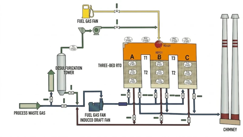
Stage 3: Three-Bed RTO at ≥760°C — VOC Thermal Oxidation
The pre-treated gas enters the three-bed RTO. At 5,000 mg/Nm³ NMHC concentration, the RTO operates fully autothermally at ≥760°C without supplementary natural gas during normal production. Key parameters: processing flow 30,000 m³/h; inlet ≤50°C; processing efficiency >99%; thermal efficiency >95%; oxidation temperature >760°C; residence time >1.2 s; combustor rating 900,000 kcal/h; natural gas at idle 118 m³/h; natural gas at idle cooling 40 m³/h; cold start consumption 250 m³; system pressure drop <3,900 Pa; weight 90 t; footprint 24×19 m.
The RTO combustion at ≥760°C oxidises all organic compounds to CO₂ and H₂O, plus generates secondary combustion products from the halogenated and heteroatom-containing species: DCM combustion generates HCl; sulfur organic combustion generates SO₂; morpholine combustion generates NH₃ and NO𝑥. These secondary combustion products must be managed by the post-RTO stages.
The RTO also incorporates a purpose-designed anti-clogging structure (detailed in Section 04 below) to manage the ammonium salt deposition that would otherwise gradually block the bottom layer of the ceramic heat storage beds.
Stage 4: Caustic Wash — Post-RTO HCl Removal
The RTO outlet gas contains HCl generated by DCM combustion (CH₂Cl₂ + O₂ → CO₂ + H₂O + 2HCl). The caustic wash (NaOH scrubber) captures this HCl: HCl + NaOH → NaCl + H₂O. Without the post-RTO caustic wash, the HCl would corrode all downstream equipment and cause acid gas stack emission exceedances under EU IED. The NaOH concentration must be continuously monitored and maintained; automatic NaOH dosing activated when pH falls below target. The caustic wash also captures any residual SO₂ from sulfur organic combustion, converting it to sodium sulfate in the wash liquor.
Stage 5: Final Water Wash — Ammonia and Residual Basic Compound Removal
After the caustic wash, the gas passes through a final water wash stage. This stage captures: (1) NH₃ generated by morpholine combustion (morpholine is a cyclic amine that produces NH₃ and other basic nitrogen compounds on thermal oxidation); (2) residual organic amines that were not fully oxidised in the RTO; (3) any mist carry-over from the caustic wash stage. The final water wash ensures the stack discharge is neutral-pH and free of basic vapour-phase compounds that could cause odour complaints or ambient air quality issues near the facility.
+Tanks+WW
5,000 mg VOC
Wash
HCl remove
Wash
Solubles
≥760°C
Anti-clog
Wash
HCl+SO₂
Wash
NH₃+amines
18 mg VOC
99.6%
Each stage addresses one specific chemical challenge. No stage can be omitted without permit non-compliance or equipment damage.
Equipment Specification
| Item | Specification |
|---|---|
| RTO processing flow | 30,000 m³/h; ≤50°C inlet; ≥760°C; >99% VOC; 24×19 m; 90 t |
| Combustor rating | 900,000 kcal/h |
| Natural gas (normal) | 0 m³/h (autothermal at 5,000 mg/Nm³) |
| Natural gas (idle) | 118 m³/h; idle cooling 40 m³/h (P: 0.03–0.07 MPa) |
| Cold start consumption | 250 m³ per cold start |
| RTO fan | 75 kW |
| Induced draft fan | 37 kW |
| RTO combustion-assist fan | 11 kW |
| Bypass fan | 30 kW |
| Circulating pumps | 11×4 kW |
| Alkali pumps | 0.55×2 kW |
| Total installed power | 200 kW (380 V, 50 Hz, 3-phase) |
| Compressed air | 30 m³ (P: 0.4–0.7 MPa) |
| Annual electricity cost | 145 kW·h/h; 116 RMB/h; 8,000 h = approx. 928,000 RMB |
| Annual natural gas cost | 0 RMB/h normal operation (autothermal) |
| Annual compressed air cost | 4 RMB/h; 8,000 h = approx. 32,000 RMB |
| Annual total operating cost | 960,000 RMB/year (120 RMB/h × 8,000 h) |
04 — Anti-Clogging RTO Design
Why Pharmaceutical API Off-Gas Blocks Standard RTO Ceramic Beds, and How the Modular Bottom-Layer Design Solves It
The anti-clogging design is the most innovative engineering feature of this installation, developed specifically for the pharmaceutical API off-gas application. Understanding why standard RTO ceramic bed design fails for this application requires understanding the ammonium salt deposition mechanism.
The Ammonium Salt Blocking Mechanism
Within the RTO three-bed switching cycle, the ceramic bed that is transitioning from outlet mode (hot, approximately 600–700°C at the outlet face) to inlet mode passes through a purge phase and then becomes the inlet bed. During the transition, the temperature of the lower (inlet-face) portion of the ceramic bed falls toward ambient as it first receives cool incoming gas. The RTO outlet gas from the previous cycle contains HCl and SO₂ generated by the combustion of the chlorinated and sulfur-containing pharmaceuticals. As this hot gas passes through the bed on its way out, and particularly as the bed transitions and cools at its lower face:
- HCl + NH₃ (from morpholine combustion) → NH₄Cl (ammonium chloride) — solid crystalline salt, sublimation temperature 338°C
- SO₂ + H₂O + NH₃ → (NH₄)₂SO₃ (ammonium sulfite) → (NH₄)₂SO₄ (ammonium sulfate) — solid crystalline salt, stable to 235°C
These ammonium salts are gaseous at the ≥760°C combustion temperature (vapour phase), but condense to solid crystals as the gas cools when passing through the cool inlet section of the ceramic heat storage bed. The salts accumulate at the bottom of the ceramic bed — the coldest section, closest to the gas inlet — progressively narrowing and eventually blocking the channels. Standard RTO designs cannot address this blockage without full system shutdown and ceramic bed replacement.
The Modular Bottom-Layer Anti-Clogging Solution
The anti-clogging design separates the bottom section of each ceramic heat storage bed into an independent modular unit, physically distinct from the main ceramic bed above it. This bottom layer is the zone where ammonium salt deposition is most severe. The modular design provides three maintenance capabilities that a standard monolithic ceramic bed does not have:
- Maintenance platform access at the bottom of the ceramic bed: A dedicated walkway/platform at the RTO base level gives maintenance personnel direct access to the bottom ceramic layer without requiring system shutdown. This enables visual inspection and condition assessment of the bottom layer without interrupting production.
- Dedicated access holes in the bottom plate: Access holes at the bottom of each bed module allow maintenance tools and flushing equipment to be inserted into the bottom ceramic layer from below, without disturbing the main ceramic bed above.
- Spray flushing capability: Spray nozzles installed in the bottom layer module can deliver water spray to dissolve ammonium salt deposits when the bottom layer temperature is cooled to approximately 50°C. Since the flushing temperature is 50°C rather than ambient, the system does not need to be fully shut down and cooled to room temperature — only the bottom layer needs to reach 50°C, which is achievable by temporarily routing hot gas around that bed. The flushing dissolves and drains the ammonium salt deposits as wash water, which is then treated in the wastewater system.
- Independent replacement of the bottom ceramic layer: If the bottom ceramic layer becomes severely blocked beyond the flushing capability, it can be replaced independently without removing the main ceramic bed above it. The bottom layer has minimal impact on the thermal performance of the main bed, and uses small-volume low-cost ceramic media. This dramatically reduces the time and cost of ceramic bed maintenance compared with replacing the full ceramic bed.
The key operational advantage is that the bottom layer flushing can be performed while the RTO continues to operate, because the three-bed configuration allows the blocked bed to be temporarily taken out of service (gas bypasses it) while it is flushed and brought back online. The flushing cycle is: (1) lower the temperature of the blocked bed to 50°C by reducing gas flow through that bed; (2) spray water to dissolve ammonium salt deposits; (3) drain the flushing water; (4) reheat the bed by restoring gas flow; (5) return to normal three-bed operation. Total maintenance interruption to that bed: approximately 2–4 hours. No production interruption to the overall system.
05 — Operational Results
Verified: 99.6% VOC Removal, Online <20 mg/m³, Grade B Enterprise, 1,195 t/yr Reduction
After commissioning, online CEMS monitoring consistently shows NMHC below 20 mg/m³ at the stack, satisfying the local permit limit of 60 mg/m³ with a large margin and meeting the national API industry exhaust standard requirement of 20 mg/Nm³ simultaneously. The enterprise has achieved Grade B emission classification. The experience summary confirms the technology selection rationale: the gas composition is complex, with diverse sources, contains halogen compounds, is high-volume, has no recovery value for the solvents given the mixture complexity, and therefore RTO heat storage thermal oxidation is the appropriate technology for this application.
.webp)
06 — Core Advantages
Five Reasons This Architecture Is Correct for Complex Pharmaceutical API VOC Streams
- ✓
The Five-Stage Chain Is the Minimum Viable Architecture for Pharmaceutical API Off-Gas With Simultaneously Chlorinated, Sulfur, and Amine Components — No Stage Can Be Omitted: Each stage serves a uniquely necessary function: alkali wash removes HCl before RTO; water wash removes water-solubles and humidity; RTO destroys VOCs at ≥99%; caustic wash removes HCl generated by DCM combustion; final water wash removes NH₃ from amine combustion. Omitting any one stage results in either RTO equipment damage (omitting alkali/water wash) or stack emission non-compliance (omitting caustic/water wash). The five-stage complexity is not over-engineering — it is exactly the minimum complexity required by the specific chemistry of this pharmaceutical API off-gas. - ✓
The Anti-Clogging Design Converts a Production-Interrupting Maintenance Event Into an Online Flushing Operation, Eliminating the Primary Reliability Risk of RTO in Pharmaceutical Applications: Without the anti-clogging design, ammonium salt blockage of the ceramic bed would require complete system shutdown for ceramic bed replacement every 6–12 months in a heavy pharmaceutical API off-gas application. Each shutdown costs production time, ceramic bed replacement cost, and labour. The anti-clogging design converts this to a 2–4 hour online flushing operation that does not require system shutdown, with full ceramic layer replacement only when flushing is no longer effective (typically every 2–3 years for the bottom layer only). This is a fundamental improvement in system lifetime economics specific to halogen and amine-containing pharmaceutical VOC applications. - ✓
At 5,000 mg/Nm³ NMHC, the RTO Operates Fully Autothermally — Annual Natural Gas Cost Is Zero During Production Hours: The high VOC loading in pharmaceutical API production (multi-solvent synthesis, high process throughput) generates sufficient exothermic heat to sustain the RTO at ≥760°C without supplementary fuel. Normal-operation natural gas consumption is 0 m³/h. The 960,000 RMB RMB annual operating cost consists entirely of electricity (145 kW·h/h) and compressed air (4 RMB/h). For a 30,000 m³/h system with five treatment stages, this represents excellent operating cost performance, particularly given the complex scrubbing chain that would add reagent costs in other designs. - ✓
Waste Heat Recovery Connection Is Provisioned on the RTO High-Temperature Outlet for Future Integration: The RTO design includes a high-temperature outlet connection for future waste heat recovery. At 5,000 mg/Nm³ NMHC and 30,000 m³/h, the RTO generates substantially more exothermic heat than is needed for autothermal operation. This surplus heat is available for steam generation, hot water production, or process heat supply at the pharmaceutical facility — where heat demand for synthesis reactor temperature control, drying, and facility conditioning is significant year-round. Waste heat recovery is provisioned but not yet installed; when implemented, it will further reduce the net annual operating cost by offsetting facility heat purchases. - ✓
99.6% VOC Destruction Meets the Strictest Pharmaceutical Industry Emission Standards With a Large Compliance Margin: The 18 mg/Nm³ actual outlet against a local permit limit of 60 mg/Nm³ and a national API industry standard of 20 mg/Nm³ provides a large compliance margin. This margin is particularly important for a pharmaceutical facility where production schedules can change rapidly, new synthesis routes may be introduced, and VOC concentration can vary significantly between production campaigns. Having an outlet consistently at 18 mg/Nm³ against a limit of 60 mg/Nm³ provides a 70% safety margin that absorbs normal production variability without risking permit exceedances.
07 — Implementation Cautions
Critical Engineering Lessons for Pharmaceutical API RTO Applications
- 🚫
Never specify a standard RTO without anti-clogging design for pharmaceutical API off-gas containing both amine and halogenated solvents — ammonium salt blockage will cause system failure within 6–12 months without it: This is not a hypothetical risk — it is a documented failure mechanism that has occurred repeatedly in pharmaceutical RTO installations globally where the anti-clogging design was not included. The ammonium chloride and ammonium sulfate salts that form at the bottom of the ceramic bed are extremely persistent deposits that cannot be removed by standard RTO purge cycles or high-temperature operation alone. Once the blockage reaches approximately 30% of the ceramic channel cross-section, the system pressure drop increases dramatically and the RTO fan can no longer maintain design airflow. System shutdown for full ceramic bed replacement is then required. The anti-clogging modular bottom layer prevents this failure mode entirely. - ⚠️
Monitor bottom layer pressure drop continuously and schedule flushing proactively before blockage becomes severe — do not wait for performance degradation before flushing: The anti-clogging design enables flushing, but the flushing is only effective if performed before the blockage is too severe. Measure pressure drop across the bottom ceramic layer separately from the main bed pressure drop using dedicated pressure taps. When the bottom layer pressure drop increases by more than 30% above the clean baseline value, plan a flushing cycle within the next planned maintenance window. Waiting until pressure drop doubles means the blockage is more severe and may require multiple flushing cycles or partial ceramic replacement instead of a single flush. - ⚠️
Any new synthesis route or solvent introduced to the gas collection system must be assessed for its impact on the ammonium salt deposition rate and the caustic wash chemistry: The five-stage chain was designed for the specific solvent profile and corrosive component levels documented at the time of design. New synthesis routes that introduce different amine compounds (triethylamine, pyridine, piperidine) or different halogenated solvents (chloroform, carbon tetrachloride, trichloroethylene) will change the rate of ammonium salt deposition and the HCl load on the caustic wash. A management of change review is mandatory before any new solvent is introduced. Fluorinated solvents (if introduced) would require HF scrubbing downstream in addition to HCl scrubbing, which the current caustic wash is not designed for. - ⚠️
Caustic wash NaOH concentration must be maintained above minimum at all times — HCl breakthrough from an exhausted caustic wash is a safety and compliance emergency: The caustic wash after the RTO captures HCl from DCM combustion. If the NaOH supply runs out or the NaOH concentration falls below the effective absorption range, HCl breaks through to the stack. At 30,000 m³/h RTO outlet with significant DCM combustion, a caustic wash failure can result in HCl stack emissions far above permit limits within minutes. The NaOH storage tank must have minimum 96 hours autonomy at the maximum expected HCl load. Implement automatic NaOH dosing activated by pH monitoring, with a separate alarm for critically low NaOH level in the storage tank.
08 — Engineering Takeaways
Four Lessons from This Pharmaceutical API RTO Project
- !
Anti-clogging design is not optional for pharmaceutical API RTO applications where amine and halogenated solvents are both present — it is a mandatory engineering requirement for long-term system reliability. The decision to include the anti-clogging modular bottom layer adds capital cost but eliminates the production-interrupting ceramic bed replacement cycle that would otherwise occur every 6–12 months. Over a 10-year system life, the anti-clogging design saves: 8–16 ceramic bed replacement events at 15–30 ten-thousand RMB each = 120–480 ten-thousand RMB in avoided capital cost; plus 8–16 production shutdown events of 1–2 days each = 8–32 days of lost production. The anti-clogging design capital investment pays back within the first 18–24 months of operation. - 2
The five-stage chain in this project, compared with the four-stage chain in Case 22 (pharmaceutical), reflects the additional morpholine amine component requiring a fifth stage (final water wash for NH₃ removal) that the other pharmaceutical installation did not have. Case 22 had: water wash → RTO → caustic wash → acid wash (four stages). Case 29 has: alkali wash → water wash → RTO → caustic wash → water wash (five stages). The difference is driven by the additional HCl in the incoming gas (requiring pre-RTO alkali wash instead of water wash) and the morpholine amine (requiring a post-caustic water wash for NH₃ instead of an acid wash for other basic compounds). This illustrates how each pharmaceutical facility generates a uniquely tailored treatment chain requirement based on its specific synthesis chemistry. - 3
At 5,000 mg/Nm³ NMHC with autothermal RTO operation, the annual operating cost of 960,000 RMB RMB for 30,000 m³/h and 1,195 t/yr VOC reduction represents good value compared with the alternative (no treatment) which would generate permit non-compliance penalties far exceeding 960,000 RMB RMB/year in an EU regulatory environment. The economics of pharmaceutical RTO are driven by the regulatory penalty for non-compliance: benzene (Group 1 carcinogen), DCM (suspected carcinogen), morpholine (Category 3 reproductive toxin), and DMSO are all compounds with strict occupational and ambient air quality limits. The annual permit compliance cost at 960,000 RMB RMB/year is justified by the regulatory risk profile of the untreated emission. - 4
The modular anti-clogging design principle is transferable to any RTO application where the gas contains simultaneously amines and acid gases (HCl or SO₂) that form salts at temperatures below 200°C. The ammonium salt deposition mechanism occurs whenever: (1) the gas contains nitrogen-bearing organic compounds or NH₃ that survive to the RTO outlet; and (2) the gas also contains HCl or SO₂ (from halogenated or sulfur-containing compounds) at the RTO outlet. Any combination of these two conditions in any industrial application (not just pharmaceuticals) creates the conditions for ammonium salt deposition in the cooler sections of the RTO ceramic bed. Other industries where this applies: fine chemicals processing amines + halogenated solvents; pesticide formulation; rubber chemical production. Specify anti-clogging design for any application with these chemical characteristics.
09 — Frequently Asked Questions
Pharmaceutical API Five-Stage RTO VOC Abatement: Ten Questions Answered
Questions from environmental permit managers, process engineers, and EHS teams at pharmaceutical API, intermediates, and formulation manufacturing facilities planning five-stage RTO VOC abatement systems under EU IED / Dutch Activities Decree requirements.
Complex Pharmaceutical API VOC? Five-Stage Treatment With Anti-Clogging RTO.
Explore the Full Range of Pharmaceutical Industry VOC Abatement Solutions
From five-stage pharmaceutical VOC chains with anti-clogging regenerative thermal oxidizers to the full range of industrial emission control solutions, our engineering team delivers EU IED–compliant systems designed for the chemical complexity of pharmaceutical API production.


