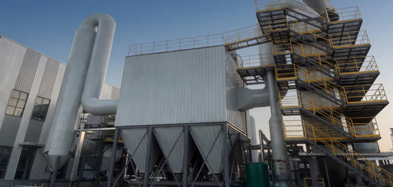
In heavy industrial applications—ranging from massive coal-fired power plants and cement kilns to metallurgical furnaces—the baghouse dust collector acts as the primary respiratory system of the facility. When this system fails, the entire production line grinds to a halt. Two of the most common, catastrophic, and deeply misunderstood failures in fabric filtration are “bag blinding” (where the microscopic pores of the filter media become permanently sealed by a cement-like mixture of moisture and sticky dust) and “ash bridging” (where dust accumulates and solidifies in the interstitial spaces between adjacent bags, creating a solid block that halts gas flow).
While many plant operators mistakenly blame the quality of the filter bag material for these issues, the root cause almost always lies deeper. The true prevention of blinding and bridging is dictated by the precision engineering of the dust collector’s internal structure. From the microscopic tolerances of the CNC-machined tube sheet and the rigidity of the support cages, to the thermodynamic insulation of the casing and the fluid dynamics of the pulse-jet cleaning system, every structural element must be perfectly optimized. In this comprehensive technical guide, we will break down how advanced internal architecture eradicates these operational nightmares.
1. The Mechanics of Blinding and Bridging
To engineer a solution, we must first understand the physics of the problem. A baghouse operates on a cyclic sequence of physical filtration and high-pressure pulse cleaning. Dust-laden gas enters the lower section of the collector. As it flows upward, inertia, diffusion, interception, and electrostatic effects cause the dust to adhere to the outer surface of the filter fabric, forming a “dust cake.”
What is Bag Blinding?
Bag Blinding is primarily a thermodynamic failure mixed with chemical reactions. When flue gas contains high levels of moisture or acidic gases (like SO2/SO3), and the internal temperature of the dust collector drops below the acid dew point, condensation occurs directly on the surface of the filter bags. This liquid mixes with the accumulated dust cake. Through capillary action, this muddy paste is drawn deep into the microscopic pores of the needle-punched felt. Once the temperature rises again, this mixture bakes into a hardened, impermeable crust. No amount of compressed air pulse-cleaning can dislodge this crust, leading to a permanent, unrecoverable spike in operational resistance (pressure drop).
What is Ash Bridging?
Ash Bridging is a mechanical and aerodynamic failure. When filter bags are installed too closely together, or when poor internal cage construction allows the long bags (often 6 to 8 meters in length) to sway and swing during the violent pulse-jet cleaning cycle, the bags physically touch each other. When they touch, the dust cake between them is compressed rather than falling into the hopper. Over time, a solid “bridge” of compacted ash builds up across multiple rows of bags. This blocks the upward flow of raw gas, creates severe localized abrasion (destroying the fabric), and eventually forces the system offline.
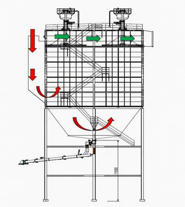
Aerodynamic Dust Accumulation Schematic
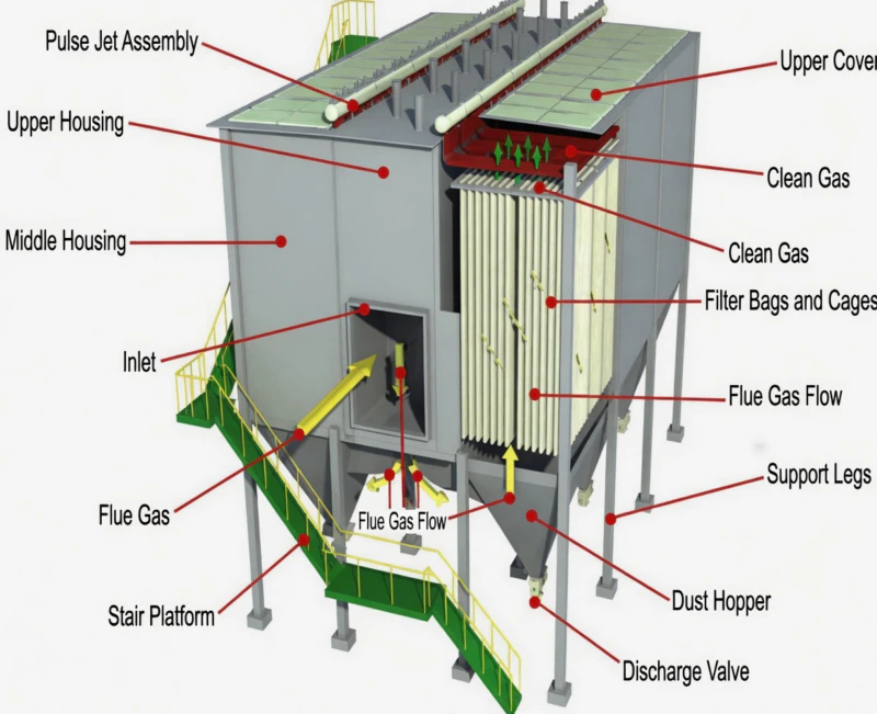
2. The Foundation of Alignment: Tube Sheet Precision Engineering
The plate, commonly referred to as the tube sheet (or flower plate), is located at the upper horizontal division inside the dust collector body. It serves as the critical physical boundary separating the dirty raw gas chamber (lower section) from the clean air plenum (upper section). A certain number of meticulously arranged plate holes are cut into this sheet to hang the filter bags and their supporting cages. If this plate is poorly manufactured, bags will hang crookedly, swinging into one another during filtration or pulse cleaning, causing immediate and catastrophic bridging.
CNC Laser Cutting for Absolute Tolerance
To eradicate bridging caused by misalignment, the plate surface is fabricated from 5-8mm thick premium low-carbon steel plate. Instead of traditional plasma or flame cutting, the holes are manufactured by exact positioning processing on a high-precision CNC laser cutting machine. This minimizes thermal deformation during processing. The center distance error between any two bag holes is strictly controlled to within ±2mm, and the deviation from the theoretical geometric position is less than ±1mm. This mathematical precision guarantees that every single bag hangs perfectly parallel, maintaining the critical interstitial spacing required for gas flow.
Surface Smoothness & Leak Prevention
The cut surface after hole opening must be extraordinarily smooth and flat. Our manufacturing standards require an inner hole surface roughness of exactly $Ra=12.5$, achieved in a single finishing step. The inner edges are polished to be completely burr-free. Furthermore, the overall plate surface must not warp under high operational temperatures; we maintain a flatness deviation of less than ±2.5mm across the entire span. This exceptional smoothness allows the snap-band of the filter bag to form an airtight, leak-proof seal without suffering abrasive damage during installation or operation.
3. The Support Cage: The Anti-Bridging Skeleton
Even with a flawlessly machined tube sheet, a poorly constructed internal cage will undermine the entire system. At high temperatures, inferior cages will warp, bend, or bow, causing the bottoms of the 8-meter-long filter bags to physically touch. Once contact is made, dust cannot escape during the cleaning pulse, and ash bridging occurs almost instantly.
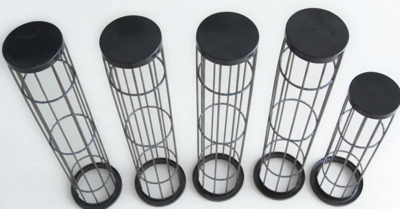
Segmented Anti-Corrosion Support Cages
Structural Rigidity & Vertical Tolerance
The bag cage is manufactured from high-strength #20 carbon steel and rigorously treated with organic silicon or specialized anti-corrosion coatings to withstand acidic atmospheres. It is designed to be simultaneously lightweight and incredibly sturdy, utilizing robust Ø4mm carbon steel longitudinal rib wires with rigid support rings generally spaced exactly 200mm apart to prevent lateral collapse.
To facilitate logistics and rapid on-site assembly for large-scale utility installations, the bag cage is designed in three interlocking sections. The three parts are connected by a highly secure, proprietary internal locking mechanism that requires no special tools, yet prevents any axial shifting.
Crucially, the cage is produced on a robotic automated assembly line. This ensures firm welds and completely smooth, burr-free weld points. A single sharp burr will act like a razor blade against the filter bag during the rapid expansion of a pulse-jet cleaning cycle, shredding the fabric. Most importantly, the engineering standard for verticality is exceptionally strict: after hanging, the maximum deviation of the distance between the bottoms of two adjacent 8-meter filter bags is engineered to be less than 40mm. This massive safety margin guarantees bags never touch, effectively eliminating the mechanical root cause of ash bridging.
4. Fluid Dynamics & Anti-Condensation Insulation
As previously stated, bag blinding is fundamentally a thermodynamic failure. When hot, high-humidity, sulfur-laden flue gas hits poorly insulated cold steel boundaries within the collector (creating “cold spots” or “thermal bridges”), the temperature drops rapidly below the acid dew point.
Additionally, to prevent heavy, abrasive dust from slamming directly into the bags—which causes structural wear and heavy localized loading—the dust collector inlet is equipped with a pre-dust removal device. The width of the inlet flue is carefully calculated to utilize a sudden reduction of flow velocity and strategic internal baffle plates to achieve pre-dust removal. By dropping coarse particles directly into the hopper before they ever reach the bags, the overall filtration load is dramatically reduced, requiring less frequent pulse cleaning and prolonging bag life.
Internal Layout & Pre-Separation Zones
5. Perfecting the Pulse-Jet Cleaning Dynamics
The pulse-jet cleaning system is the active mechanism that reverses the accumulation of dust. Operating at high pressures (typically 0.3 to 0.6 MPa), compressed air is fired down into the bags for a fraction of a second, creating a shockwave that flexes the bag outward, shattering the dust cake so it can fall into the ash hopper. However, if this system is not structurally optimized, it can actually exacerbate bridging.
Blowpipe Alignment & Venturi Tubes
The blowpipe must be perfectly aligned over the exact center of each bag cage. If the blowpipe nozzle is misaligned by even a few millimeters, the supersonic jet of air will strike the inner wall of the bag rather than traveling straight down. This causes uneven cleaning (leaving dust patches that promote bridging) and rapidly wears a hole through the side of the bag. To ensure perfect alignment and maximize the induction of secondary cleaning air, precision-cast Venturi tubes are integrated into the top of each cage collar, guiding the shockwave uniformly down the entire 8-meter length.
Gas Collecting Box Optimization
To provide ample volume for the clean air to stabilize and to give the pulse-jet system enough clearance to operate efficiently, the height of the gas collecting box above the tube sheet is engineered to be 800-1000mm. This expansive volume solves the problem of excessive uniform resistance distribution and prevents uneven filtration air velocity across the bag matrix, ensuring every bag shares an equal load.
6. Final Defense: Synergistic Filter Material Selection
Once the internal structure is perfected to prevent mechanical swaying, misalignment, and thermodynamic condensation, the final step in preventing blinding is selecting the appropriate filter media. The filter material is the primary barrier, and its chemical and thermal limits define the boundaries of the system.
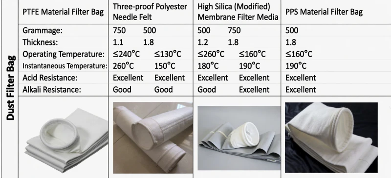
Premium Industrial Filter Media
PTFE (Polytetrafluoroethylene)
The absolute gold standard for chemical resistance. Capable of withstanding operating temperatures up to 240°C, it is practically immune to acid and alkali attacks, making it the premier choice for Waste-to-Energy incinerators and highly corrosive chemical off-gases.
PPS (Polyphenylene Sulfide)
The backbone of coal-fired power plants. With a 500g weight and operating capacity up to 160°C, it handles sulfur-rich environments exceptionally well. When treated with PTFE membranes, it becomes highly hydrophobic (water-repellent), severely limiting the risk of moisture-induced blinding.
Modified High-Silica
When temperatures surge past the melting points of standard polymers (up to 260°C), inorganic fibers like High-Silica are deployed. Widely used in metallurgy and cement kilns, they maintain structural integrity and prevent pore collapse under extreme thermal shock.
Eliminate Dust Collector Downtime Forever
Is your plant suffering from crippling pressure drops, frequent bag blinding, or the massive maintenance costs of ash bridging? The problem isn’t just your bags; it’s the internal architecture. Contact our global environmental engineering team for a comprehensive structural review, CFD analysis, and advanced retrofit blueprint.


