Case Study · VOC Abatement
How a major integrated refinery and petrochemical group achieved 99.5% VOC destruction from 16,000 m³/h of highly concentrated, H₂S-bearing, benzene-series-laden off-gas from wastewater treatment and condensation recovery systems — deploying a safety-critical alkali wash + water wash pre-treatment chain before a three-bed RTO operating at ≥800°C with triple-redundant LEL monitoring, explosion-proof design throughout, and steam-preheat for autothermal performance optimisation.
Three-Bed RTO
H₂S Removal Pre-Treatment
Explosion-Proof LEL Interlock
Refinery Wastewater Off-Gas
01 — Industry Background
Petrochemical VOC Control: Safety-First Engineering for Explosive, Toxic, and Highly Variable Refinery Off-Gas Streams
The petrochemical and oil refining sector is one of the largest industrial sources of VOC emissions globally. Petroleum and its refinery products consist of complex mixtures of hydrocarbons, of which the lighter, low-boiling fractions have significant volatility. Across the crude oil extraction, refining, storage, transport, and sales chain, small amounts of lighter hydrocarbons are inevitably released to atmosphere due to process equipment limitations. Petrochemical facility VOC emissions originate from storage tanks, process vessel vents, equipment fugitive leaks, wastewater treatment plant surfaces, and condensation recovery system off-gases.
The petrochemical sector’s VOC abatement challenge has three characteristics that are unique compared with printing, pharmaceutical, or coating industry applications: (1) Extreme safety criticality — petrochemical VOC streams contain flammable hydrocarbons (oil gas, benzene series), toxic gases (H₂S), and potentially pyrophoric compounds, making LEL management a life-safety requirement rather than a permit compliance requirement; (2) Corrosive gas composition — H₂S and benzene-series compounds create a highly corrosive environment requiring specialised materials throughout, from collection pipework to RTO combustion chamber; (3) High concentration variability — wastewater treatment plant off-gas concentrations can swing dramatically as waste loading changes, requiring a buffering strategy (alkali wash tower as buffer volume) and a robust concentration management system.
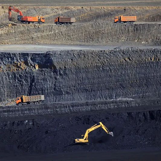
The enterprise in this case study is a large integrated refinery and petrochemical group with 8,000 employees, total assets of 65 billion RMB, crude oil first-processing capacity of 10.5 million tonnes per year, and multiple downstream petrochemical product lines including high-sulfur coking, petrochemical products, and group trading, logistics, and retail operations. The facility is a major provincial energy chemical production centre. The VOC abatement project addresses the oil-gas recovery device tail-gas and high-concentration off-gas from the wastewater treatment plant within the refinery complex.

“Petrochemical off-gas safety management requires that concentration never exceeds 25% LEL at any point in the collection and treatment system. The buffer tank downstream of the alkali wash stage — equipped with its own LEL monitor — is the critical safety element that provides adequate emergency shutdown response time between a concentration spike event at any individual source and the system reaching an unsafe condition at the RTO inlet.”
— Engineering Technical Summary, Petrochemical Industry VOC Treatment Project
02 — Pollution Profile
Refinery Wastewater Off-Gas: H₂S, Benzene, Oil Gas at 8,000 mg/Nm³ NMHC With 60% Humidity and Explosive Composition
The off-gas in this project originates from two source categories within the refinery complex:
- Oil-gas recovery device tail-gas (two units: east and west zones): These are the residual tail-gas streams from the refinery’s oil vapour recovery systems after condensation and absorption. East zone unit processes 3,300 m³/h intermittently at NMHC <1 g/Nm³; west zone unit processes 3,500 m³/h intermittently at NMHC <5 g/Nm³; combined design maximum 6,800 m³/h.
- High-concentration off-gas directly collected from the wastewater treatment plant: Off-gas from sewage adjustment tanks (3,000×2 m³; 1,014 m³/h), oil-separation tanks (300×2 m³; 100.8 m³/h), sludge concentration tanks (60×4 m³; 68 m³/h), flotation tanks (300×2 m³; 100.8 m³/h), oil-containing wastewater pools (3.8×4.7×2; 150 m³/h), sedimentation tanks (29.6×16.6×1.5; 2,949 m³/h), aeration tanks (23.8×14.7×1; 1,400×2 m³/h), combining to a design flow of 8,700 m³/h with NMHC 5,000–8,000 mg/Nm³, average of 3,500 mg/Nm³ at NMHC, and 140 mg/Nm³ average benzene-series concentration.
The combined standard process gas volume is 16,000 m³/h (17,465 Nm³/h at 25°C). The critical safety-determining feature of this off-gas is the simultaneous presence of H₂S (hydrogen sulfide from refinery process chemistry), benzene-series compounds (benzene, toluene, xylene from crude oil fractionation residues), and oil gas hydrocarbon vapours — all in gas-phase at concentrations that can approach the LEL under peak loading conditions. The humidity is high at 60%, and the gas carries no particulate matter (all sources are liquid-surface evaporation). The O₂ content is 21% (ambient air entrained with vapour).
| Parameter | Initial Concentration | Actual Outlet | EU IED / NER Limit |
|---|---|---|---|
| NMHC (total VOCs) | 8,000 mg/Nm³ (peak) | 40 mg/Nm³ | IED 2010/75/EU ≤20 mg/Nm³ |
| Benzene | Present (benzene series) | ≤2 mg/Nm³ | IED ≤1 mg/Nm³ |
| Toluene | Present | ≤5 mg/Nm³ | IED ≤3 mg/Nm³ |
| Xylene | Present | ≤8 mg/Nm³ | IED ≤12 mg/Nm³ |
| H₂S, benzene series, oil gas | Present (gas phase) | Removed by alkali wash | IED / IPPC Site permit |
| Humidity | 60% | — | — |
| Standard gas volume | 16,000 m³/h (design) | — | — |
| Process gas volume | 17,465 Nm³/h at 25°C | — | — |
| Annual VOC reduction | ~685 t/year | Verified | — |
Critical safety note: The fan response distance from the alkali wash buffer tank to the emergency bypass valve must be ≥60 m (up to 90 m is achievable in this configuration). This distance ensures adequate mechanical response time for the emergency bypass damper to operate after a high-LEL alarm signal, preventing flammable gas from entering the RTO ceramic bed system under explosive conditions. Shortening this distance below 60 m is a safety violation.
03 — Treatment Solution
Four-Stage Chain: Alkali Wash + Water Wash + Buffer Tank + Three-Bed RTO With Triple LEL Interlock
The treatment system addresses two simultaneous requirements: (1) safety management of a flammable, toxic, and explosive off-gas stream; and (2) VOC destruction to >99% efficiency. These two requirements drive different aspects of the system design. The safety management drives the alkali wash, buffer tank, triple LEL monitoring, explosion-proof design, and emergency bypass. The VOC destruction drives the three-bed RTO specification at ≥800°C with >95% thermal recovery.
Stage 1: Organic Gas Front-End Collection and Isolation
Organic gas from wastewater treatment tanks and oil-gas recovery device tail-gas is collected at the front end through flame arresters and pre-treatment equipment before isolation. Flame arresters (also called flame traps) are installed at each individual source connection to prevent any ignition event at the RTO from propagating back through the collection manifold to the liquid surface of the wastewater tanks, which would cause a tank fire or explosion. All individual source connections are fitted with isolation valves to allow individual units to be isolated for maintenance without shutting down the entire system.
Stage 2: Alkali Wash (H₂S and Acid Gas Removal)
Gas collected by the intermediate induced draft fan enters the alkali wash system to remove acidic components (primarily H₂S and any CO₂ or SO₂ present). H₂S must be removed before the RTO for two reasons: (1) H₂S combustion in the RTO generates SO₂, which would require a downstream FGD stage that is not part of this installation’s design; (2) H₂S-bearing gas is toxic to maintenance personnel and requires confined space entry procedures that would complicate the RTO ceramic bed inspection programme. The alkali wash tower removes mist generated in the washing process via a mist eliminator before the gas passes to the buffer tank.
Stage 3: Buffer Tank + LEL Monitoring (3-of-2 Voting Logic)
After the alkali wash, the gas enters a buffer tank equipped with its own LEL concentration monitor. The buffer tank serves two critical functions simultaneously: (1) it provides time-averaging of VOC concentration spikes, ensuring the gas entering the RTO has a more uniform concentration than the raw source streams which can vary significantly in short time periods; (2) it provides the response time volume needed for the emergency bypass system to operate correctly when a high-LEL event is detected.
Triple LEL monitoring is installed at the common collection manifold using a 3-unit LEL monitoring system in 2-of-3 voting logic (three take two mode): if any two of the three LEL sensors simultaneously read above the 25% LEL threshold, the emergency bypass activates automatically. This 2-of-3 voting arrangement provides both safety redundancy (one sensor failure does not disable the interlock) and false-alarm prevention (one sensor malfunction does not cause unnecessary production shutdown). The minimum sensor response distance from the buffer tank to the emergency bypass valve is 60 m to ensure adequate mechanical actuation time.
Under non-normal conditions (concentration spike above 25% LEL), gas is directed through the activated carbon emergency bypass to short-time atmosphere venting (a brief emergency measure). Under normal conditions, the gas enters the three-bed RTO fan for thermal oxidation.
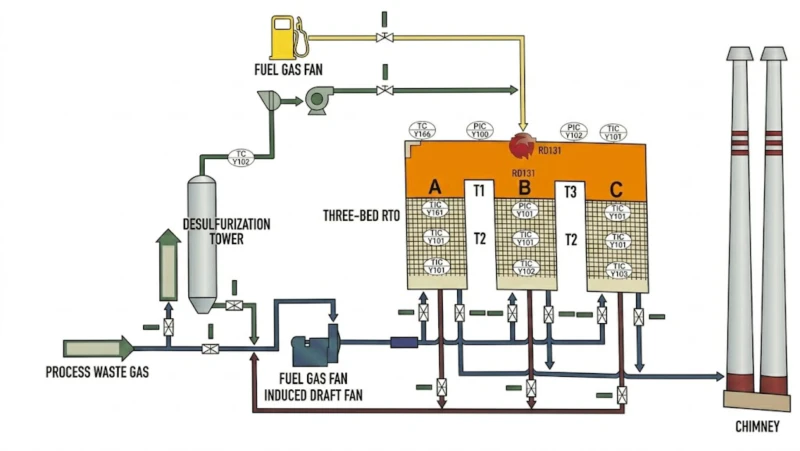
Stage 4: Three-Bed RTO at ≥800°C
Under normal conditions, the pre-treated gas (H₂S-free, concentration-buffered, below 25% LEL) enters the three-bed RTO. The RTO raises the gas to ≥760°C (design operating target) with the organic compounds thermally oxidised to CO₂ and H₂O. A steam pre-heater is installed before the RTO to raise the VOC-laden gas temperature, reduce moisture content through partial condensation, raise VOC concentration, and reduce the concentration of large-molecule oily substances in the gas, preventing accumulation in the RTO inlet manifold that could cause safety hazards.
The RTO operates in standard three-bed valve switching mode: one bed in inlet mode (pre-heating incoming gas through the pre-heated ceramic), one bed in outlet mode (post-treating gas while the ceramic cools), one bed in purge mode (clearing residual VOC before the bed transitions to outlet). The high-temperature emergency bypass (partial) handles high-temperature scenarios by mixing with a mixing box before stack discharge when the combustion chamber temperature exceeds the maximum operating limit.
Tanks + Oil
Recovery
Arresters
Each Source
Wash
H₂S remove
Tank
3×LEL
Preheat
Drying
≥760°C
>99% VOC
→ Stack
40 mg VOC
⭐ New or safety-critical equipment in this project. Emergency bypass (activated carbon) routes high-LEL gas around the RTO to atmosphere in safety events.
Key Equipment Parameters
| Item | Specification |
|---|---|
| RTO processing flow | 16,000 m³/h; inlet temp ≤30°C; 25×15 m footprint; weight 60 t |
| Destruction / thermal efficiency | >99% / >95% |
| Combustion chamber residence time | >1.2 s; oxidation >760°C |
| Combustor rating | 600,000 kcal/h |
| Natural gas (cold start 3 h) | 71 m³/h (P: 0.03–0.06 MPa) |
| Natural gas (idle operation) | 35 m³/h |
| Cold start gas consumption | 176 m³ per cold start event |
| System pressure drop | <3,000 Pa |
| Fan power | 75 kW; 5,000 Pa; φ600 mm duct |
| LEL monitoring | 3 units; 2-of-3 voting logic; emergency bypass at >25% LEL |
| Electrical classification | ExdIIBT4 explosion-proof throughout |
| Annual electricity cost (8,400 h) | 324,240 kW·h; approx. 197,786 RMB/year (0.61 RMB/kWh) |
| Annual compressed air cost | 20 m³/h; approx. 25,200 RMB/year (0.15 RMB/m³) |
| Annual natural gas cost (estimate) | 25,200 m³/h rate; approx. 37,800 RMB/year (1.5 RMB/m³) |
| Annual condensate steam cost | 688,800 kg/h rate; approx. 121,228 RMB/year (176 RMB/t) |
| Annual production water cost | 1,260 t/year; approx. 1,890 RMB/year (1.5 RMB/t) |
04 — Core Advantages
Five Reasons This Architecture Is the Right Approach for Petrochemical Refinery VOC Abatement
- ✓
Alkali Wash Before the RTO Removes H₂S and Prevents SO₂ Generation in the Combustion Chamber: H₂S is present in refinery wastewater off-gas at concentrations that would, if burned in the RTO without pre-treatment, generate SO₂ at concentrations requiring a downstream limestone-gypsum FGD stage (adding significant capital and operating cost). The alkali wash removes H₂S before the RTO inlet, converting it to sodium sulfide in the wash liquor. This keeps the RTO combustion chemistry clean (only hydrocarbon + O₂ → CO₂ + H₂O) without acid gas complications, and eliminates the need for any post-RTO desulfurization equipment. - ✓
Triple LEL Monitoring With 2-of-3 Voting Logic Provides Both Safety Redundancy and False-Alarm Resistance: A single-sensor LEL interlock has two failure modes: sensor failure that disables the safety interlock (dangerous), and sensor malfunction that triggers unnecessary production shutdown (costly). The 3-sensor, 2-of-3 voting arrangement eliminates both failure modes: any single sensor failure is detected because the two remaining sensors maintain consistent readings, and a single sensor malfunction does not trigger the interlock because the other two sensors are still below the threshold. For a petrochemical refinery environment where LEL sensor calibration drift is a known operational risk, this voting architecture is the minimum acceptable configuration for a life-safety interlock. - ✓
Buffer Tank After Alkali Wash Provides the Concentration Time-Averaging and Response Time That the Safety System Requires: Refinery wastewater treatment off-gas concentrations vary episodically as different wastewater streams are processed and as biological treatment tank activity fluctuates. Without a buffer tank, a VOC concentration spike from one tank could arrive at the RTO inlet within seconds of the spike occurring at the source. The buffer tank volume provides the time delay needed for the LEL monitoring system to detect the spike, the control logic to respond, and the emergency bypass valve to physically operate — a minimum response time of 60 seconds at 16,000 m³/h flow. The alkali wash tower also serves as a secondary buffer in this architecture. - ✓
Steam Pre-Heating Before the RTO Addresses the Three Challenges of High-Humidity, Oily, High-Concentration Gas: The 60% humidity and oil mist content of the refinery wastewater off-gas create specific problems for the RTO: (1) high humidity lowers the adiabatic flame temperature and increases supplementary fuel consumption; (2) oil mist can condense and accumulate in the RTO inlet manifold, creating a fire risk; (3) high concentrations can cause uncontrolled exothermic reactions in the RTO ceramic bed before the combustion chamber. Steam pre-heating simultaneously reduces relative humidity (by raising gas temperature without adding humidity), volatilises oil mist residues, and pre-dilutes the effective VOC concentration entering the combustion zone. This is a petrochemical-specific design feature not found in printing or pharmaceutical RTO installations. - ✓
ExdIIBT4 Explosion-Proof Design Throughout Is Mandatory for Petrochemical Zone Classification: The entire VOC collection and treatment system operates in an area classified as a hazardous zone under ATEX Directive 2014/34/EU. All electrical equipment (fan motors, actuators, instruments, lighting, control panels) must be certified to ExdIIBT4 explosion-proof classification or better for Group IIB gases (which includes the benzene-series and oil gas mixtures present here). Using standard-rated electrical equipment in a petrochemical VOC abatement system is not merely a regulatory violation — it is a genuine ignition risk in a system designed to handle flammable gas at near-LEL concentrations.
05 — Operational Results
Verified Performance: 99.5% VOC Removal and 685 Tonnes/Year Reduction
.webp)
Annual operating cost breakdown (8,400 operating hours): electricity at 324,240 kWh (0.61 RMB/kWh) = 197,786 RMB; compressed air at 20 m³/h (0.15 RMB/m³) = 25,200 RMB; natural gas (estimated) at 1.5 RMB/m³ = 37,800 RMB; condensate steam 688,800 kg total (176 RMB/t) = 121,228 RMB; production water 1,260 t (1.5 RMB/t) = 1,890 RMB. Total annual operating cost approximately 383,904 RMB (approximately 38.4 ten-thousand RMB equivalent). This is exceptionally low operating cost for a refinery VOC abatement system, reflecting the small scale (16,000 m³/h vs 120,000 m³/h in the pharmaceutical case) and the VOC-rich feed enabling near-autothermal RTO operation.
06 — Implementation Cautions
Six Critical Safety and Engineering Lessons for Petrochemical VOC Abatement
- 🚫
The LEL concentration at the system inlet must never exceed 25% LEL — this is a safety-of-life requirement that overrides all production continuity considerations: The emergency bypass system must activate instantly and automatically when the 2-of-3 LEL interlock trips. There must be no override capability from the process control room that would allow operators to bypass the LEL interlock to maintain production throughput. The interlock logic must be implemented as a hardwired safety relay (SIL-rated per IEC 61511), not as a software PLC function, to ensure it operates independently of any DCS failure mode. Monthly functional testing of the emergency bypass valve operation is mandatory. - ⚠️
The minimum fan response distance (60 m) from buffer tank to emergency bypass valve must be maintained — do not shorten the collection manifold to save installation cost: The 60 m minimum distance is a safety engineering requirement, not an aesthetic preference. At the design flow of 16,000 m³/h in a φ600 mm duct, gas velocity is approximately 15 m/s. At 60 m distance from the buffer tank to the emergency bypass valve, the transit time for a concentration spike to travel from the detection point to the bypass valve is approximately 4 seconds. Adding the 2-of-3 logic processing time and valve actuation time (~2–3 seconds), the total response time window is approximately 6–7 seconds. This is the minimum acceptable response time for a petrochemical LEL safety interlock. Shortening the manifold below 60 m reduces this safety margin below the minimum. - ⚠️
Gas corrosivity from H₂S and benzene compounds requires the highest anti-corrosion specification for all equipment — standard carbon steel will fail within 1–2 years: The combination of H₂S (which causes hydrogen embrittlement and sulfide stress cracking in carbon steel), benzene-series solvents (which cause swelling and degradation of standard elastomers), and high humidity creates one of the most corrosive gas environments in industrial off-gas treatment. All collection manifolds, alkali wash vessels, buffer tanks, pre-treatment equipment, and RTO inlet manifolds must be constructed from 316L stainless steel minimum, with FRP or glass flake epoxy lining on large-bore ductwork and vessels. The equipment service life is particularly emphasized in the experience summary as a documented operational challenge — the gas corrosivity is strong and equipment service life does not reach design requirements unless the highest anti-corrosion specification is applied from the outset. - ⚠️
Steam pre-heater performance must be verified under maximum humidity conditions to prevent oily condensate accumulation in the RTO inlet manifold: The steam pre-heater must raise the gas temperature sufficiently to reduce relative humidity below the dew point of the heavy oil vapours present in the refinery wastewater off-gas. If the pre-heater is undersized or if the steam supply pressure drops during winter cold conditions, the relative humidity at the RTO inlet may remain above the dew point, allowing oil condensation in the inlet manifold. Accumulated oily condensate in the RTO inlet manifold can auto-ignite when the RTO comes to operating temperature, creating an internal fire hazard. Monthly inspection of the RTO inlet manifold for oil accumulation is recommended from year 1 of operation. - ⚠️
Maintaining stable gas composition is the primary operational challenge — strictly control input material sources and furnace operation: The experience summary explicitly identifies two primary operational risks: (1) unstable CO content causing over-limit spikes; (2) fluctuating moisture and dust levels with peaks exceeding design values. The response measures are: strictly control raw material sources to maintain system operating stability; control furnace (wastewater treatment) operation to ensure stable gas composition. This requires active coordination between the wastewater treatment operations team and the VOC treatment system operators, with a formal communication protocol for any planned wastewater composition changes. - ⚠️
Continually improve operator safety training and revise emergency response plans to reflect actual operational experience: Petrochemical facility operators must understand both the normal RTO operating procedures and the emergency response procedures for H₂S release events, LEL exceedance events, and RTO over-temperature events. The emergency response plans must be kept current with the actual installed configuration, because any modifications to the collection system, addition of new wastewater sources, or changes to the alkali wash chemistry can change the response requirements. Annual emergency response drills covering all three emergency scenarios (H₂S release, LEL exceedance, RTO over-temperature) should be conducted with all operators who may be on duty when an event occurs.
07 — Engineering Takeaways
Four Lessons From This Petrochemical VOC Abatement Project
- !
Safety architecture (alkali wash + buffer + triple LEL + ExdIIBT4 design) is not a compliance overhead for petrochemical RTO applications — it is the engineering foundation that makes the installation viable. Unlike printing or pharmaceutical RTO applications where the safety measures are significant but the primary objective is emission compliance, petrochemical RTO applications have a primary objective of safe operation in a genuinely explosive hazard environment. The alkali wash removes the most dangerous compound (H₂S) before it reaches the RTO, the buffer tank provides the response time the safety system needs, the triple LEL interlock prevents explosive mixtures from entering the RTO, and the ExdIIBT4 classification prevents electrical ignition. Any of these missing makes the installation unsafe regardless of what the CEMS data shows. - 2
Alkali wash before RTO for H₂S removal eliminates the need for downstream FGD and makes the overall system significantly simpler and lower-cost than the alternative. If H₂S-bearing petrochemical off-gas were sent directly to the RTO, the combustion chemistry would generate SO₂ at concentrations requiring a downstream limestone-gypsum FGD stage (adding capital cost equivalent to 30–40% of the RTO cost and an ongoing limestone reagent cost). The alkali wash captures H₂S at its source, preventing SO₂ generation, at a capital cost of approximately 10–15% of the RTO cost and an ongoing NaOH reagent cost. For petrochemical applications where H₂S is present, the alkali wash before RTO is the economically superior option in most cases. - 3
Steam pre-heating is the petrochemical-specific design feature that addresses humidity and oily condensate simultaneously — it is not found in printing or pharmaceutical RTO applications. The 60% humidity and oil mist content of refinery wastewater off-gas create problems that are absent in printing (dry solvent vapours) and pharmaceutical (relatively low oil content) applications. Steam pre-heating before the RTO is the solution specifically developed for petrochemical applications: it simultaneously reduces relative humidity, volatilises oil mist before it can condense in the RTO manifold, and helps raise the gas temperature toward the RTO inlet requirement. Engineers designing RTO systems for printing or pharmaceutical applications who are asked to adapt their designs for a petrochemical application must add the steam pre-heater as a mandatory modification. - 4
At 16,000 m³/h and 8,000 mg/Nm³ NMHC, the annual operating cost is approximately 38.4 ten-thousand RMB — among the lowest in any of the 23 case studies reviewed. The combination of small scale (16,000 m³/h vs 60,000–120,000 m³/h in other cases) and high inlet VOC concentration (approaching autothermal operation without supplementary fuel) produces very low operating cost in this installation. The VOC-rich refinery wastewater off-gas is energetically dense: at 8,000 mg/Nm³ NMHC, the chemical energy in the VOC stream is sufficient to maintain the RTO combustion chamber temperature without supplementary natural gas during normal production, making the electricity cost for the fan (197,786 RMB/year) the dominant cost item.
08 — Frequently Asked Questions
Petrochemical Refinery VOC RTO Abatement: Ten Questions Answered
Questions from HSE managers, process engineers, and environmental permit teams at petroleum refinery, petrochemical, and energy chemical facilities planning alkali wash + RTO VOC abatement systems under EU IED / Dutch ATEX / Omgevingswet requirements.
Ready to Solve Your Petrochemical Refinery VOC Challenge Safely?
Explore the Full Range of Regenerative Thermal Oxidation Solutions
From three-bed RTO systems with explosion-proof design for petrochemical refinery VOC abatement to the full range of industrial emission control solutions, our engineering team delivers EU IED–compliant systems with the safety architecture that hazardous zone applications demand.


