Case Study · Industrial Emission Control
How a global power battery leader achieved 81.5% combined SNCR+SCR denitrification efficiency and 97.9% desulfurization from rotary kiln lithium carbonate production off-gas with SO₂ inlet concentrations reaching 12,000 mg/Nm³ — deploying a dual-line SNCR+SCR+limestone-gypsum FGD+lime treatment system adapted for the extreme variability of battery-grade lithium carbonate sintering off-gas chemistry.
SNCR+SCR Combined Denitrification
Limestone-Gypsum FGD
Lithium Carbonate Sintering
Ultra-Low Battery Industry Emission
01 — Industry Background
Power Battery Lithium Carbonate Production: A Rapidly Expanding Sector With Demanding Emission Challenges
Lithium carbonate is a fundamental raw material for lithium battery manufacturing. Global demand is growing rapidly on the back of electric vehicle adoption and grid-scale energy storage expansion, with output growing from 4.1 t/a in 2014 to 39.5 million tonnes in 2022 at a 28% compound annual growth rate, and projections pointing to 110 million tonnes capacity by 2025 and 51.79 million tonnes actual production in 2023 (year-on-year growth 31.1%). Battery-grade lithium carbonate production capacity requirements will only increase as EV markets continue to scale, driving further investment in production facilities and their associated environmental compliance infrastructure.
The enterprise in this case study is one of the leading power battery companies globally, and one of the few companies with full power battery industry chain coverage. Listed on a major domestic exchange in 2015 and on the Swiss Stock Exchange in 2022 as the first power battery company in Switzerland, its main business encompasses lithium batteries for mobility applications, energy storage systems, and power distribution equipment. The “solid-state battery” product announced in 2024 achieves energy density of 3,500 Wh/kg and volumetric energy density of 800 Wh/L, with 30,000-cycle service life and theoretical range exceeding 300,000 km. The enterprise also produces approximately 100,000 distribution units annually.
Lithium carbonate production uses rotary kiln sintering to convert lithium-bearing raw materials (primarily mica-derived lithium salts) into battery-grade lithium carbonate. The sintering chemistry involves high-temperature reaction of sulfate and carbonate compounds that drives the release of SO₂ in concentrations far exceeding those of conventional industrial boilers or power plants. As market demand for lithium carbonate grows and production facilities scale, the flue gas purification system for rotary kiln sintering becomes a critical compliance and operational bottleneck. This project deploys limestone-gypsum FGD combined with SNCR+SCR denitrification to achieve ultra-low emission targets and advance the facility’s green development credentials.
.webp)
02 — Pollution Profile
Lithium Carbonate Rotary Kiln Off-Gas: Extreme SO₂ Variability as the Defining Challenge
The facility operates two rotary kiln production lines, each equipped with a cyclone dust collector + cooling unit + bag filter dust collector, processing flue gas from the sintering of lithium carbonate battery material. The kiln is fired on natural gas. The standard flue gas volume per production line is 120,000 Nm³/h (185,897 Nm³/h at process conditions, 150°C). After cooling, the flue gas is collected at the FGD system.
The defining feature of lithium carbonate rotary kiln off-gas is the extraordinary variability of SO₂ concentration. During the sintering reaction cycle, lithium sulfate compounds decompose to release SO₂: the average SO₂ concentration entering the desulfurization absorber is approximately 4,645 mg/Nm³, but peak concentrations can reach 12,000 mg/Nm³, with baseline levels at approximately 12% oxygen-corrected concentration of around 809 mg/Nm³ NOx. The SO₂ concentration swing of 10:1 between baseline and peak (from approximately 1,200 mg/Nm³ to 12,000 mg/Nm³) requires the FGD system to be designed for the peak condition while maintaining stable operation and gypsum quality during the baseline and mid-range periods.
| Parametro | Concentrazione iniziale | Designed Outlet | EU IED / NER Limit |
|---|---|---|---|
| NOx (as NO₂) | 809 mg/Nm³ (at 12% O₂, baseline ammonia content 12%) | ≤150 mg/Nm³ | IED 2010/75/EU: 150 mg/Nm³ |
| SO₂ (average at FGD inlet) | 4,645 mg/Nm³ avg; peak 12,000 mg/Nm³ | ≤100 mg/Nm³ | Dutch Activities Decree NER |
| Particulate matter (PM) | 658 mg/Nm³ | ≤30 mg/Nm³ | Dutch Activities Decree NER ≤5 mg/Nm³ |
| HCl | 3.7 mg/Nm³ | ≤10 mg/Nm³ | IED BAT ≤10 mg/Nm³ |
| HF | 6.74 mg/Nm³ | ≤6 mg/Nm³ | IED BAT ≤1 mg/Nm³ |
| Acid mist (fog) | 191 mg/Nm³ | ≤20 mg/Nm³ | IED BAT |
| Standard flue gas (per line) | 120,000 Nm³/h | — | — |
| Process flue gas (per line) | 185,897 Nm³/h at 150°C | — | — |
| SCR flue gas volume | 273,846 Nm³/h (combined 2 lines) | — | — |
| Kiln exit temperature | 380–420°C (at SCR/SNCR installation point) | — | — |
Key design challenge: SO₂ at 4,645 mg/Nm³ average and 12,000 mg/Nm³ peak represents an inlet concentration approximately 3× the maximum inlet concentration of a typical coal-fired power plant FGD. The 12,000 mg/Nm³ peak combined with the need to achieve ≤100 mg/Nm³ outlet (99.2% removal efficiency at peak) requires the FGD to be designed for extreme overloading above the average operating condition. This drives the need for oversized absorber towers, high liquid-to-gas ratios, and conservative calcium-to-sulfur stoichiometric ratios in the system design.
03 — Treatment Solution
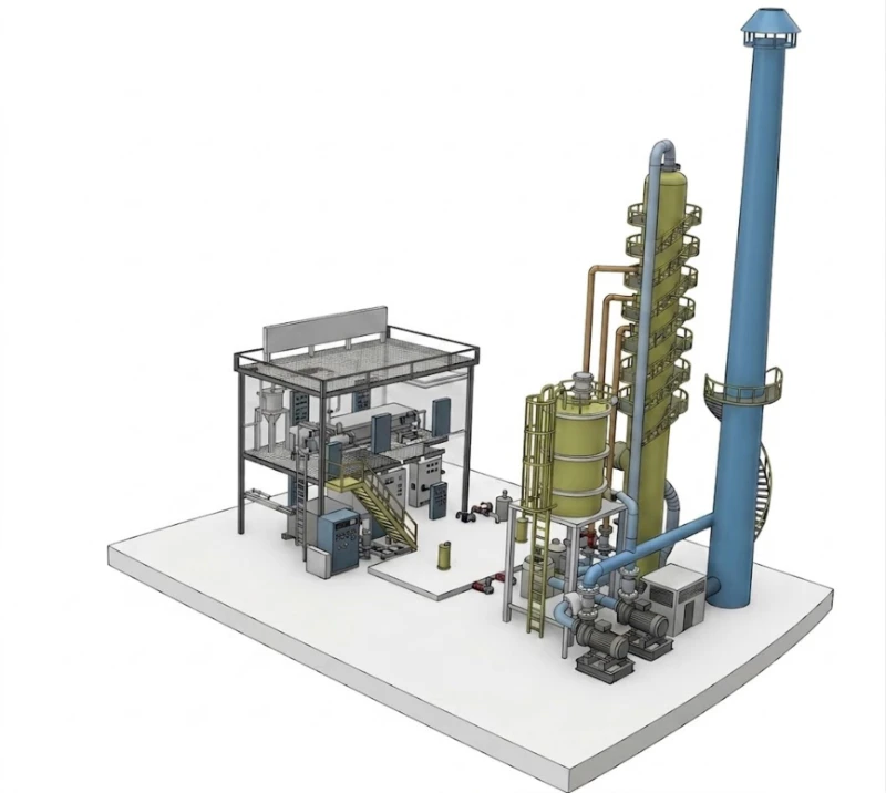
Dual-Line Treatment Architecture: SNCR at Kiln Exit + SCR + Limestone-Gypsum FGD + Lime Desulfurization
The project covers two rotary kiln production lines. The treatment system for each line includes: cyclone pre-dedusting → gas cooling → bag filter dust removal → flue gas collection → SNCR+SCR denitrification → limestone-gypsum FGD → lime post-desulfurization. This upgrade was implemented on the existing rotary kiln production line by adding an SCR denitrification unit and a limestone-gypsum + limestone (lime) desulfurization system to achieve ultra-low emission compliance. For the second production line at the rear of the facility, a limestone-gypsum desulfurization system is simultaneously deployed to ensure SO₂ outlet ≤100 mg/Nm³, while flue gas small-hour averages achieve compliance across all parameters.
SNCR Denitrification at Kiln Exit (380–420°C Zone)
The SCR system installation position is selected at the multi-tube dust collector outlet of the rotary kiln exit, where temperature is maintained at 380–420°C. At this temperature and with SO₂ content below 4,600 mg/Nm³, a mid-temperature SCR catalyst can be used. The SCR reactor internal catalyst is designed with a 2+1 layer configuration (2 active layers + 1 spare layer). The reducing agent is ammonia water, and the front-end SNCR uses a single nozzle spray system. Front-end SNCR can guarantee the denitrification efficiency satisfies the denitrification target. For the desulfurization tower spray layers, their opening quantity is adjusted based on online monitoring values, achieving stable flue gas ultra-low emission discharge.
SCR Reactor Key Parameters
Flue gas volume 273,846 m³/h (combined 2 lines); flue gas temperature 350°C at SCR; initial NOx 809 mg/Nm³; initial PM 658 mg/Nm³; actual O₂ ≤15.2%; NOx outlet 150 mg/Nm³; catalyst pore count 18; catalyst porosity 72.59%; catalyst layers 2+1 (1 spare layer); catalyst modules per layer 12; total catalyst volume 31.104 m³; design temperature 230°C; maximum operating temperature 350°C; minimum operating temperature 200°C; urea injection rate 111.919 kg/h; denitrification efficiency 88%; ammonia slip ≤3 ppm; pressure drop ≤600 Pa; soot blowing method: pulse-jet blow.
.webp)
Limestone-Gypsum FGD Absorber Tower (φ4.4 m, 120,000 m³/h)
The FGD tower is the most heavily loaded piece of equipment in the system, receiving SO₂ at an average of 4,645 mg/Nm³ and peak of 12,000 mg/Nm³. To achieve ≤100 mg/Nm³ outlet under peak loading (99.2% removal efficiency), the tower is specified with an exceptionally high liquid-to-gas ratio of 30 and 4 spray layers. Key parameters: flue gas volume 120,000 m³/h per tower; flue gas temperature 150°C; SO₂ inlet 4,645 mg/Nm³; SO₂ outlet 100 mg/Nm³; calcium-to-sulfur ratio 1.1; gas velocity <3.5 m/s; tower internal diameter φ4.4 m; liquid-to-gas ratio 30; 4 spray layers; single pump flow 900 m³/h; slurry settling time 6 h; limestone operating consumption 718 kg/h (maximum); gypsum production 1,488 kg/h (maximum); gypsum moisture content ≤15%; mist eliminators: 2-layer screen mist eliminator; intermediate limestone storage capacity 50 m³; 7-day autonomy.
Process Flow Summary
380–420°C
NH₃ injection
900°C zone
Pre-dedusting
Bag Filter
350°C
2+1 layers
φ4.4 m
97.9% SO₂
Post-FGD
→ Stack
⭐ New or upgraded equipment in this project
Key Equipment Parameters at a Glance
| Equipment | Key Specification |
|---|---|
| Induced draft fan | 220,000 m³/h; 5,000 Pa; 250–300°C; 335 kW per unit; 50 Hz variable speed |
| SCR reactor | 273,846 m³/h; 350°C; 2+1 catalyst layers; 31.104 m³ catalyst; 88% NOx efficiency; ≤3 ppm NH₃ slip |
| FGD absorber tower | φ4.4 m; 120,000 m³/h; L/G=30; 4 spray layers; 900 m³/h pump; 718 kg/h limestone; 1,488 kg/h gypsum |
| Gypsum production (max) | 1,488 kg/h; moisture content ≤15%; commercially reusable |
| Limestone storage | 50 m³; 7-day autonomy at maximum consumption |
| Max system power | 1,047.52 kW actual; 1,186.67 kW total installed |
| Annual electricity cost (8,000 h) | Approx. 301.7 ten-thousand RMB equivalent at 0.36 RMB/kWh |
| Annual water cost | Approx. 8.8 ten-thousand RMB equivalent (5.5 t/h; 2 RMB/t) |
| Annual limestone cost | Approx. 172.32 ten-thousand RMB equivalent (718 kg/h; 300 RMB/t) |
04 — Core Advantages
Why SNCR+SCR Combined Denitrification and Limestone-Gypsum FGD Is the Right Architecture for High-SO₂ Lithium Carbonate Kilns
- ✓
SNCR at the High-Temperature Kiln Zone Maximises Combined Denitrification Efficiency: The SNCR injection position at the rotary kiln exit (where the temperature window of 850–1,100°C is available) enables efficient thermal NOx decomposition without catalyst. The SNCR removes a portion of the NOx load before the gas enters the SCR reactor, reducing the total NOx load at the SCR inlet. This SNCR pre-reduction allows the downstream SCR reactor to achieve the overall 81.5% combined denitrification efficiency (from 809 mg/Nm³ to ≤150 mg/Nm³) with a catalyst volume and pressure drop that would not be achievable if the SCR had to handle the full inlet NOx load alone. - ✓
Mid-Temperature SCR at 350°C Is Viable Because the Natural Gas Kiln Contains No SO₂ at the SCR Inlet: The SCR reactor is positioned at the multi-tube dust collector outlet, where the gas temperature is approximately 350–380°C and — critically — where SO₂ from the sintering reaction has not yet fully entered the gas stream (or has been partially removed by the upstream dust collector). Since the natural gas fuel contains no sulfur, the SO₂ is entirely a sintering chemistry product. The SCR placement exploits the window before the peak SO₂ release point to use mid-temperature catalyst without ammonium bisulfate poisoning. This contrasts with the FGD inlet (where SO₂ is at full 4,645 mg/Nm³ average concentration), which would immediately destroy a standard SCR catalyst. - ✓
L/G Ratio of 30 and 4 Spray Layers Achieves 97.9% FGD Removal From 4,645 mg/Nm³ Average: Standard power plant FGD designs use L/G ratios of 8–15 for SO₂ inlet concentrations of 1,000–3,000 mg/Nm³. The lithium carbonate kiln FGD tower operates at L/G=30 — more than twice the standard power plant ratio — with 4 spray layers rather than the typical 3. This combination of high liquid-to-gas ratio and additional spray contact provides the extended absorption residence time needed to achieve 97.9% desulfurization from the 4,645 mg/Nm³ average inlet, while maintaining adequate performance margin for the 12,000 mg/Nm³ peak condition where 99.2% removal is needed to stay within the 100 mg/Nm³ outlet limit. - ✓
Online Monitoring-Based FGD Spray Layer Control Optimises Reagent Consumption Across the Full SO₂ Variability Range: The desulfurization tower spray layer opening quantity is adjusted based on online SO₂ monitoring data from both the FGD inlet and outlet. During baseline SO₂ periods (when inlet is at the lower range of the 4,645 mg/Nm³ average), fewer spray layers are activated, reducing pump energy consumption and limestone slurry circulation rate. During peak SO₂ events, all 4 spray layers are activated simultaneously. This dynamic spray layer management significantly reduces the annual energy and reagent cost compared with running all 4 layers continuously at maximum flow rate regardless of actual SO₂ load. - ✓
Gypsum By-Product at 1,488 kg/h (Maximum) Has Direct Commercial Value: The exceptionally high gypsum production rate (1,488 kg/h maximum, reflecting the 4,645 mg/Nm³ average SO₂ inlet concentration) makes this FGD system a significant gypsum producer. At ≤15% moisture content, the gypsum meets the quality specification for construction material reuse (wallboard substrate, cement additive) if chloride content is within the EN 13279-1 specification limit. This positions the FGD system as a value-generating by-product process rather than simply a compliance cost centre, partially offsetting the 718 kg/h limestone reagent cost through gypsum sales revenue. - ✓
Limestone-Gypsum FGD Design Principles Applied: Seven Advantages for Lithium Carbonate Applications: The limestone-gypsum process was selected for this application for the same seven principles validated in power plant applications: (1) low energy consumption and operating cost; (2) gypsum by-product manageable without secondary pollution; (3) small footprint and rational flow design; (4) computer simulation-optimized design; (5) optimized gas velocity for uniform absorption; (6) limestone raw material is widely sourced and low-cost; (7) tower internals using counter-current spraying and mist eliminators to reduce tower wall deposition. These principles are directly applicable to lithium carbonate rotary kiln FGD, and the operational experience from thousands of power plant FGD installations provides a strong knowledge base for system design and troubleshooting.
05 — Operational Results
Verified Compliance Data and Annual Cost Summary
.webp)
Maximum system running power: 1,047.52 kW (actual). At 8,000 annual hours and 0.36 RMB/kWh equivalent, annual electricity cost is approximately 301.7 ten-thousand RMB equivalent. Annual water cost: approximately 8.8 ten-thousand RMB equivalent (5.5 t/h, 2 RMB/t). Annual limestone cost: approximately 172.32 ten-thousand RMB equivalent (718 kg/h at 300 RMB/t). Gypsum by-product revenue at 1,488 kg/h maximum production partially offsets these reagent costs.
06 — Implementation Cautions
Critical Engineering Considerations for Lithium Carbonate Rotary Kiln Off-Gas Treatment
- ⚠️
Upstream SO₂ concentration fluctuations (from production line processing conditions) cause FGD system overload and impact desulfurization efficiency — the primary risk: The primary documented operational risk is that upstream process fluctuations cause SO₂ concentration swings that drive the FGD system into overloaded operation, causing system discharge instability. With SO₂ peak concentrations at 12,000 mg/Nm³ and average at 4,645 mg/Nm³, the FGD is already sized for extreme overloading above a typical power plant condition. Any additional SO₂ spike above the 12,000 mg/Nm³ design peak can push the system into genuine non-compliance. Implement SO₂ monitoring at both the FGD inlet (before absorption) and outlet (after absorption) with real-time feedback to the spray layer control, and establish a protocol for advance notification from the production team before any operating changes that affect sintering chemistry and SO₂ release rate. - ⚠️
SNCR nozzle positioning in the rotary kiln requires careful attention — the kiln wall is mainly caused by high-temperature evaporation, and the flue gas contains high dust that easily causes catalyst blockage: The project experience explicitly identifies two SNCR-specific risks: (1) the injection pipeline in the rotating section of the rotary kiln must be carefully handled — kiln wall adhesion is primarily caused by high-temperature evaporation processes, requiring nozzle materials and installation methods that can withstand thermal cycling; (2) since the flue gas at the SNCR injection point contains high dust loading, the SCR catalyst downstream is susceptible to blockage by particulates. The SCR soot blowing system (pulse-jet blow) must be operated at the calibrated frequency from commissioning day, and the first catalyst inspection at 6 months should include a comprehensive pressure drop measurement across all catalyst layers to verify that blockage rate is within acceptable bounds. - ⚠️
SNCR denitrification temperature is critical — only within the appropriate temperature range can ideal denitrification efficiency be achieved: The SNCR injection point must maintain the gas temperature in the 850–1,100°C window for effective thermal NOx decomposition. Below 850°C, the NOx-NH₃ thermal reaction is too slow for effective reduction; above 1,100°C, the ammonia oxidises to form additional NOx rather than reducing it. The SNCR injection point temperature must be continuously monitored, and the ammonia water flow rate must be adjusted in real time to compensate for temperature variations across the injection zone. A non-uniform temperature distribution across the kiln cross-section (common in rotary kilns with variable feed rates) can create simultaneously over-temperature zones and under-temperature zones, reducing effective SNCR removal efficiency. - ⚠️
The extreme FGD limestone consumption rate (718 kg/h maximum) requires reliable supply chain management and adequate on-site storage: At 718 kg/h maximum limestone consumption and 50 m³ on-site storage (7-day autonomy), the limestone supply chain must deliver a reliable weekly supply. Any supply interruption that depletes the limestone storage below the minimum operating level will force reduction in SO₂ treatment capacity, creating a compliance risk within hours. Implement supply contract provisions requiring guaranteed delivery frequency, maintain a minimum inventory trigger level (e.g. 3-day remaining supply) that triggers an automatic purchase order, and document the contingency procedure for temporary FGD rate reduction during supply interruption events. - ⚠️
FGD slurry pH and calcium sulfite oxidation must be actively managed to prevent scaling and maintain gypsum quality: At the high SO₂ inlet concentrations of this application, the FGD slurry loop accumulates sulfite and sulfate at rates far above power plant FGD practice. The pH management windows are critical: when primary scrubber circulation loop pH falls below 4.5, add slurry and maintain pH at 4.5–5.5; when secondary scrubber circulation loop pH falls below 5.5, add slurry and maintain at 5.5–6.5. The oxidation fan must run continuously to ensure adequate air supply for calcium sulfite oxidation to gypsum — incomplete oxidation produces calcium sulfite scaling in the absorber rather than the filterable gypsum crystals that can be dewatered to ≤15% moisture. - ⚠️
Flue gas entering the desulfurization system with high SO₂ concentration may cause FGD overloaded operation — adopt high-efficiency calcium-based desulfurization reagent and improve desulfurization efficiency: Based on the documented experience summary, the critical point of this process is: when upstream SO₂ peaks at 12,000 mg/Nm³, the FGD system can be near its absorption capacity limit even with L/G=30 and 4 spray layers. At this point, the limestone slurry must be at optimal pH with fully activated oxidation, and all 4 spray layers must be running at maximum flow. If the limestone quality degrades (lower CaCO₃ purity), or if any spray nozzle blockage reduces effective coverage, or if the slurry pH has drifted low, the system will fail to meet the ≤100 mg/Nm³ outlet during the peak event. Regular (weekly) spray nozzle inspection is required to ensure full coverage is maintained at all times.
07 — Engineering Takeaways
Four Lessons from This Power Battery Lithium Carbonate Kiln Off-Gas Project
- 1
SNCR+SCR combination is essential when the NOx inlet is above 600 mg/Nm³ and the target outlet is ≤150 mg/Nm³ — neither technology alone can deliver the required 81.5% removal efficiency at this FGD inlet condition. SNCR alone achieves 30–50% NOx removal but with limited selectivity and sensitivity to temperature variation. SCR alone at 273,846 m³/h would require an impractically large catalyst volume to achieve 81.5% removal from 809 mg/Nm³. The SNCR pre-reduction reduces the SCR inlet NOx to a manageable level while the SCR provides the precise, high-efficiency reduction needed to meet the ≤150 mg/Nm³ limit reliably. The combined SNCR+SCR architecture is the standard recommendation for any application where inlet NOx exceeds 600 mg/Nm³ and outlet must be below 200 mg/Nm³. - 2
Design the FGD for the peak SO₂ condition, not the average — for a 10:1 variability ratio, the difference in system sizing is substantial. The average SO₂ of 4,645 mg/Nm³ and the peak of 12,000 mg/Nm³ require the same target outlet of ≤100 mg/Nm³. At average inlet, removal efficiency is 97.8%; at peak inlet, 99.2% is required. Designing for average conditions (97.8% removal) and scaling the system accordingly would result in compliance exceedances during every peak SO₂ event. The FGD must be sized for 99.2% removal efficiency under the 12,000 mg/Nm³ peak condition, which drives the L/G=30 specification and 4-spray-layer design. The compliance margin during average conditions (outlet well below 100 mg/Nm³) is the natural result of a correctly peak-sized system. - 3
Online monitoring-based dynamic spray layer control converts variable SO₂ load from an operational problem into an operational advantage. The spray layer activation control based on online SO₂ monitoring turns the 10:1 SO₂ variability from a system stress factor into an energy and reagent optimisation opportunity. During baseline SO₂ periods, 1–2 spray layers are sufficient; during peak periods, all 4 are activated. This dynamic management reduces pump electricity consumption and limestone slurry circulation during low-SO₂ periods by 50–75% versus always running all 4 layers, delivering significant annual OPEX savings while maintaining full compliance across all SO₂ conditions. - 4
Gypsum production at 1,488 kg/h from high-SO₂ lithium carbonate FGD is large enough to require an active gypsum marketing strategy, not just a disposal plan. At maximum production rate, this FGD generates approximately 35.7 tonnes of gypsum per 24-hour operating day. This is a commercially significant volume that warrants establishing a supply agreement with a construction gypsum processing facility before commissioning, rather than treating gypsum disposal as an afterthought. If the gypsum quality (chloride content, moisture, heavy metal content) meets the applicable standards for construction material reuse, the revenue from gypsum sales can meaningfully offset the 718 kg/h limestone reagent cost.
08 — Frequently Asked Questions
Power Battery Lithium Carbonate Rotary Kiln Off-Gas Treatment: Ten Questions Answered
Questions from environmental permit managers, process engineers, and sustainability teams at power battery material production facilities planning SCR denitrification and high-SO₂ FGD upgrades under EU IED / Dutch Activities Decree requirements.
Ready to Achieve Ultra-Low Emission Compliance for Your Battery Materials Kiln?
Explore the Full Range of Industrial Emission Control Solutions
From SNCR+SCR denitrification and high-SO₂ limestone-gypsum FGD for lithium carbonate rotary kilns to regenerative thermal oxidation systems for industrial VOC abatement, our engineering team delivers EU IED–compliant solutions for the most demanding new energy battery materials emission control requirements.


