Case Study · Industrial Emission Control
How a high-performance lithium-ion battery anode material graphitization producer achieved 99.85% desulfurization efficiency, SO₂ outlet below 18 mg/Nm³, and zero visible white plume — from an Acheson furnace off-gas stream carrying SO₂ at up to 20,000 mg/Nm³ and particulates at 300 mg/Nm³.
Limestone-Gypsum Wet FGD
SNCR Denitrification
Magnetic Plume Abatement
Battery Anode Material Emission Compliance
01 — Industry Background
The Graphitization Furnace Emission Challenge at the Heart of the EV Battery Supply Chain
Anode materials are one of the four core raw materials of lithium-ion batteries, and also a strategic emerging industry in their own right, aligned with national priorities in the 14th Five-Year Plan and 2035 Long-Range Objectives. The rapid global expansion of electric vehicle adoption has made lithium battery anode materials one of the highest-growth industrial subsectors globally, with 2023 shipment volumes reaching 178.3 ten-thousand tonnes (year-on-year growth of 15.1%) and projections pointing toward 800 ten-thousand tonnes by 2030.
Graphitization is the highest-energy and highest-emission step in the anode material production chain. Acheson furnaces heat the carbon precursor material to temperatures exceeding 2,500°C over a cycle of 64 hours, during which the sulfur compounds naturally present in petroleum coke and coal tar pitch feedstocks are driven off as SO₂. The resulting SO₂ concentration in the furnace off-gas is extraordinarily high — routinely reaching 11,302 mg/Nm³ at the desulfurization absorber inlet, with peak values documented at 20,000 mg/Nm³. This makes graphitization furnace off-gas among the highest-concentration SO₂ streams encountered in any manufacturing sector globally.
As environmental regulations tightened through the 2024 Pollution Discharge Permit Management Regulations and the Action Plan to Accelerate Pollution and Carbon Reduction, the requirement for graphitization furnace off-gas to achieve ultra-low emission became unavoidable. The technical challenge is not merely to reduce SO₂ from 11,302 to ≤18 mg/Nm³ — a 99.84% reduction — but to do so while simultaneously managing particulate matter, NOx, HCl, HF, CO, and the visible white plume that makes non-compliance immediately and publicly obvious.
“Graphitization furnace SO₂ at 11,302 mg/Nm³ is not a boiler or power plant desulfurization problem. It is an acid gas treatment problem of the type encountered in sulfuric acid manufacturing. Achieving 99.85% removal efficiency to reach 18 mg/Nm³ outlet while simultaneously managing particulates, NOx, and visible white plume requires a purpose-designed multi-technology system, not an adaptation of standard industrial scrubbing practice.”
— Engineering Technical Summary, Graphitization Industry Dust Removal / Desulfurization / Denitrification Project
02 — Pollution Profile
Acheson Furnace Off-Gas: The Most SO₂-Intensive Stream in Battery Materials Manufacturing
The facility specializes in R&D, production, and sales of new-energy lithium battery anode materials and graphitization-related products. It serves international high-end customers, is counted among the world’s top-three anode material suppliers, and holds 1 enterprise brand project, 2 registered trademarks, and 19 patents.
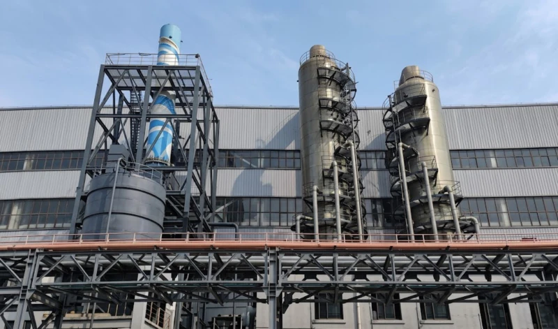
The Acheson furnace operates on a 64-hour cycle at extreme temperatures. The raw flue gas exits at 170°C and carries the following pollutants simultaneously:
- SO₂ at 11,302 mg/Nm³ inlet to FGD absorber (raw gas peak documented at 20,000 mg/Nm³). This is the defining pollutant: a 99.85% removal requirement to reach ≤18 mg/Nm³ outlet is among the most demanding desulfurization specifications in any industrial sector.
- Particulate matter at 300 mg/Nm³ (raw gas), comprising primarily graphite and carbon dust from the furnace charge material. Target outlet: ≤5 mg/Nm³ — a 98.3% overall reduction requirement.
- NOx at 100 mg/Nm³ from high-temperature combustion air reactions. Target outlet: ≤100 mg/Nm³ via SNCR denitration upstream.
- CO at 100 mg/Nm³. Requires CO safety monitoring and combustion management upstream of any enclosed treatment stage.
- HF at 5 mg/Nm³ and HCl at 15 mg/Nm³. Both are corrosive acid gases that drive the corrosion-resistant materials specification for all wetted components.
- High temperature variability: Raw gas at 170°C must be reduced to below 120°C by the energy recovery heat exchanger before the induced draft fan and further reduced to below 40°C by the MPA unit inlet. This temperature management requirement drives significant auxiliary equipment investment.
- Extreme SO₂ cycle variation: During the 64-hour Acheson furnace cycle, SO₂ concentration peaks at approximately 20,000 mg/Nm³ and can remain elevated for periods of 2–3 hours. The desulfurization system must be designed for the maximum SO₂ load under the most unfavorable large-flue-gas, maximum-SO₂ operating condition.
| Parameter | Raw Gas / Inlet to Treatment | Outlet (Design) | Regulatory Limit |
|---|---|---|---|
| SO₂ | 11,302 mg/Nm³ avg (peak 20,000) | ≤18 mg/Nm³ | 18 mg/Nm³ |
| Particulate matter (PM) | 300 mg/Nm³ | ≤5 mg/Nm³ | 5 mg/Nm³ |
| NOx | 100 mg/Nm³ | ≤100 mg/Nm³ | 100 mg/Nm³ |
| CO | 100 mg/Nm³ | ≤100 mg/Nm³ | 100 mg/Nm³ |
| HF | 5 mg/Nm³ | ≤5 mg/Nm³ | 5 mg/Nm³ |
| HCl | 15 mg/Nm³ | ≤15 mg/Nm³ | 15 mg/Nm³ |
| Visible white plume | Present | None (invisible) | No visible white plume |
| Flue gas volume (rated, FGD) | 140,000 Nm³/h | — | — |
| MPA treated volume | 100,000 Nm³/h | — | — |
| Raw gas temperature | 170°C | — | — |
| Applicable standard | EU Industrial Emissions Directive (IED 2010/75/EU) and the Dutch Activities Decree (Activiteitenbesluit milieubeheer) | ||
03 — Engineering Requirements
Why Standard Industrial Desulfurization Approaches Cannot Solve the Graphitization SO₂ Problem
The engineering challenge of this project was not simply selecting a technology — it was designing an integrated multi-stage system that addresses all six pollution parameters simultaneously while managing the extreme cyclical variability of SO₂ concentration across the 64-hour Acheson furnace cycle.
Design for Peak SO₂ Load, Not Average
The FGD system must achieve compliance under the maximum SO₂ scenario: maximum flue gas volume coinciding with maximum SO₂ concentration (20,000 mg/Nm³). Designing for the average (11,302 mg/Nm³) would result in compliance exceedances during the 2–3-hour peak periods of each furnace cycle.
Energy Recovery as an Integral Design Element
The 170°C raw gas carries recoverable thermal energy. An energy conversion and recovery heat exchanger is specified as the first treatment stage to reduce flue gas temperature to 119.46°C before the induced draft fan, improving fan operating conditions and reducing downstream equipment thermal loading while recovering useful heat energy for the facility.
Dual-Stage Absorption for Extreme SO₂
Single-tower limestone-gypsum FGD cannot achieve 99.85% SO₂ removal from 11,302 mg/Nm³ to ≤18 mg/Nm³ in one pass. A two-stage absorption architecture — primary scrubber followed by secondary scrubber — is required, with inter-stage pH monitoring and slurry management to maintain optimal absorption efficiency across both towers continuously.
White Plume Elimination via Downstream MPA
After the two-stage FGD, the post-scrubber gas is still saturated with water vapor and residual acid mist. A Magnetic Plume Abatement unit (BLCNXB-10W, 100,000 Nm³/h) is specified as the final polishing stage, installed after the energy recovery heat exchanger that raises the gas temperature to above 80°C to prevent visible condensation plume formation.
Gypsum By-Product Management
The limestone-gypsum FGD process generates calcium sulfate (gypsum) as a by-product at up to 2,618 kg/h. The system must incorporate gypsum dewatering to achieve a moisture content below 15% for practical handling and disposal. The gypsum must comply with by-product quality standards that enable reuse as construction material rather than disposal as waste.
Corrosion Resistance for HF and High-SO₂ Service
The combination of SO₂ at 11,302 mg/Nm³ and HF at 5 mg/Nm³ creates an exceptionally aggressive corrosive environment. All wetted surfaces in the FGD absorbers, gypsum handling system, and MPA unit must be specified in materials rated for this combined acid service. Standard carbon steel or mild stainless steel is not acceptable for any wetted component.
SNCR Integration for NOx Compliance
SNCR (Selective Non-Catalytic Reduction) denitration is integrated into the treatment train to address the 100 mg/Nm³ NOx limit. The SNCR reagent injection point must be positioned within the temperature window (850–1,100°C) within the furnace off-gas ductwork for effective NOx decomposition without ammonia slip.
Safety: Fire, Explosion, and CO Hazard Management
Graphitization furnace off-gas contains combustible carbon dust and CO at 100 mg/Nm³, both of which create fire and explosion risks in enclosed treatment equipment. Fire prevention, explosion protection, and anti-corrosion measures must be designed into the system, and all equipment interlocks must incorporate CO concentration monitoring with automatic bypass capability.
04 — Treatment Solution
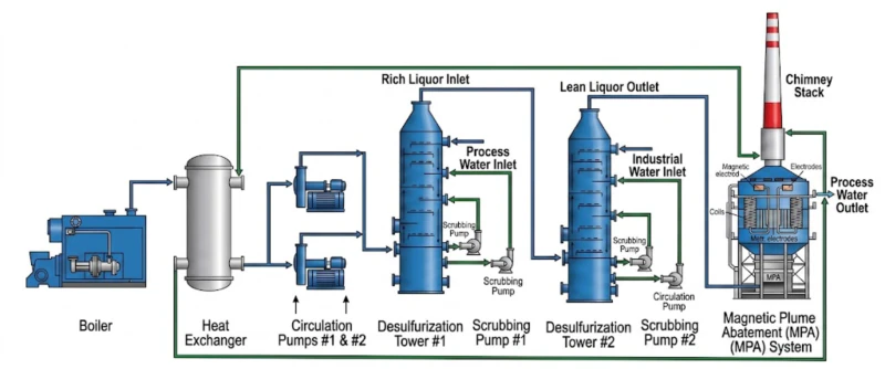
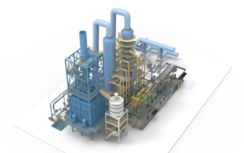
Integrated Four-Stage Treatment System: Energy Recovery → Dual-Tower FGD → MPA → Clean Stack
The treatment system integrates three proven technologies in series, each addressing a distinct set of pollutants from the graphitization furnace off-gas stream. The combination was selected to exploit the complementary strengths of each technology while eliminating each technology’s blind spots through the other stages.
Stage 1: Energy Recovery Heat Exchanger (170°C → 119.46°C)
Raw graphitization furnace off-gas at 170°C is first directed to the energy recovery heat exchanger, where the thermal energy content of the hot gas is transferred to a working medium for facility use. Gas temperature is reduced to 119.46°C before the induced draft fan, improving fan operating conditions and extending equipment life. The heat exchanger handles 85,000 Nm³/h with a 934 m² heat transfer area and equipment pressure drop of 273 Pa.
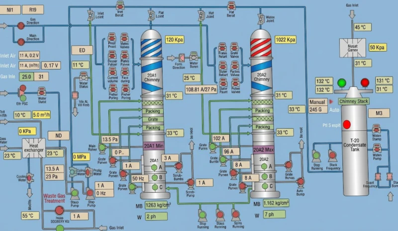
Stage 2: Induced Draft Fan → Two-Stage Limestone-Gypsum FGD (140,000 Nm³/h)
Two counter-current limestone-gypsum absorption towers treat the 140,000 Nm³/h gas stream. The primary scrubber incorporates a 2-layer screen mist eliminator; the secondary scrubber has a 1-layer screen mist eliminator and 1 bundle mist eliminator set. Between the two towers, an online liquid level monitoring and pH monitoring system enables real-time slurry replenishment and inter-stage liquid pH control — ensuring the slurry circuit remains optimally balanced across the full 64-hour furnace cycle without manual intervention. Key FGD parameters: limestone consumption 1,858 kg/h (max), gypsum production 2,618 kg/h (max), gypsum moisture content below 15%, limestone storage capacity 150 m³ with 3-day autonomy.
Stage 3: SNCR Denitrification
SNCR denitration with 50% estimated removal efficiency reduces NOx from 100 mg/Nm³ to meet the outlet specification. The SNCR injection system operates within the high-temperature zone of the off-gas ductwork where thermal decomposition of the NOx-reagent complex is effective without requiring a dedicated SCR catalyst bed.
Stage 4: Magnetic Plume Abatement (100,000 Nm³/h)
After the two-stage FGD, the cleaned gas passes through a second energy recovery heat exchanger (energy conversion and temperature-raising unit) that raises the gas temperature from approximately 45°C to above 80°C, reducing the water vapor dew point margin and improving conditions for MPA plume capture. The gas then enters the BLCNXB-10W Magnetic Plume Abatement unit for final deep polishing and white plume elimination before discharge through the main stack.
Furnace
170→119°C
Fan
FGD Tower
FGD Tower
HX →80°C
(BLCNXB-10W)
Stack
MPA Unit Key Technical Parameters
| Parameter | Specification |
|---|---|
| MPA Unit Model | BLCNXB-10W |
| Layout Type | Tower-external, stand-alone module |
| Air Flow Orientation | Bottom-entry, top-exhaust (direct) |
| Purification Efficiency | ≥95% |
| Inlet Mixed Pollutant Concentration | 100 mg/Nm³ |
| Outlet Mixed Pollutant Concentration | ≤5 mg/Nm³ |
| System Resistance | 300 Pa |
| Treated Flue Gas Volume | 100,000 Nm³/h |
| MPA Inlet Gas Temperature | <40°C (post-FGD); raised to >80°C by temp-rise HX before MPA |
| System Pressure | ±5,000 Pa design |
| Equipment Dimensions (W×D) | 7,900 × 7,900 mm plan |
| Equipment Height | 17,000 mm |
| Magnetic Energy Generator | BLEMG-2K |
| MPA Average Power Consumption | 80 kW |
| MPA Runtime Load Factor | 195 (operating load index) |
05 — Core Advantages
Why Limestone-Gypsum FGD + SNCR + MPA Is the Right Architecture for Graphitization Furnace Off-Gas
- ✓
Limestone-Gypsum FGD Achieves 99.85% SO₂ Removal from 11,302 mg/Nm³ Raw Gas: The verified desulfurization efficiency of 99.85% — reducing inlet SO₂ from 11,302 to outlet average of 8 mg/Nm³ — is exceptional even by the standards of coal power plant FGD, which typically treats SO₂ concentrations one order of magnitude lower. The limestone-gypsum process was selected for this application because it uses abundant, low-cost reagent (limestone is widely sourced and price-stable), produces a commercially usable by-product (gypsum for construction), and has the lowest liquid-to-gas ratio of all wet FGD chemistries for comparable removal efficiency. The intra-tower mist eliminator design and the inter-stage pH monitoring system are the specific engineering innovations that enable this performance at the graphitization SO₂ concentration level. - ✓
Energy Recovery Converts a Thermal Waste Stream into a Facility Asset: The 170°C raw gas carries significant thermal energy that is extracted by the upstream heat exchanger before the FGD system, reducing the temperature to 119.46°C. This recovered energy is returned to the facility as useful heat, improving overall energy efficiency and reducing the net energy cost of the treatment system. A second heat exchanger downstream of the FGD raises gas temperature before the MPA unit, further optimizing plume elimination performance. The dual heat exchanger configuration makes this system both thermally and environmentally optimized. - ✓
Computer Simulation Optimization Delivers Low Resistance and Energy-Efficient Design: Advanced computational fluid dynamics simulation was used to optimize the gas velocity distribution within the FGD absorber towers, minimize internal resistance, and achieve uniform reagent-gas contact. This simulation-driven design approach produces a system with lower electricity consumption and higher reagent utilization than empirically designed towers of equivalent capacity, while ensuring compliance under worst-case SO₂ load conditions. - ✓
Gypsum By-Product Enables Zero-Waste Operation: The 2,618 kg/h maximum gypsum production rate from the FGD reaction is not waste — it is a commercially usable construction material when dewatered to below 15% moisture content. The system incorporates a vacuum belt filter or equivalent dewatering system to achieve this specification, enabling the gypsum to be sold or used in on-site construction material applications. This eliminates the solid waste disposal cost and regulatory burden that would otherwise arise from treating gypsum as industrial waste. - ✓
Verified Compliance Performance Across All Six Regulated Parameters Simultaneously: The system achieved: desulfurization efficiency 99.85% (SO₂ outlet 8 mg/Nm³, vs. limit 18); dust removal efficiency 98.4% (PM outlet 2.4 mg/Nm³, vs. limit 5); denitrification efficiency 55%; NOx outlet 45 mg/Nm³ (vs. limit 100); HF outlet 1 mg/Nm³ (vs. limit 5); HCl outlet 3.5 mg/Nm³ (vs. limit 15); and zero visible white plume. All six parameters are simultaneously at substantial compliance margins below their respective limits. - ✓
One-Button Restart Capability for Slurry Circulation System: The design incorporates a one-button automatic restart function for the slurry circulation system following a planned or emergency shutdown, eliminating the complex manual valve sequencing previously required. This significantly reduces operator workload and the risk of human error during system restarts, which are critical periods for compliance exceedance risk in high-SO₂ FGD applications.
06 — Operational Results
Verified Compliance Data: All Six Pollutant Parameters Below Regulatory Limits
The integrated system achieved all compliance targets simultaneously, with substantial margins below regulatory limits across all monitored parameters:
The maximum running load of the complete system is 1,522.55 kW. At 24 h/day continuous operation, the daily electricity cost is 13,154.832 RMB (at 0.36 RMB/kWh). For 8,000 annual operating hours, the annual electricity cost is approximately 4,384.944 ten-thousand RMB. Annual water consumption is approximately 4.85 t/h; at 5 t/h for 24 h/day and a water unit price of 2 RMB/t, the daily water cost is 240 RMB, translating to 80 ten-thousand RMB per year. Limestone consumption at 1,858.632 kg/h at 300 RMB/t results in an annual limestone cost of 445.92 ten-thousand RMB.
07 — Implementation Cautions
Critical Engineering and Operational Lessons for Graphitization Furnace FGD Applications
- ⚠️
Slurry concentration management is the most critical operational parameter in high-SO₂ limestone-gypsum FGD: The project’s documented operational experience specifies: (1) primary scrubber limestone slurry liquid level must not exceed overflow level; when adding water while adding limestone, concentration must be controlled at 15%–20%; (2) when primary scrubber circulation loop pH falls below 4.5, add slurry and maintain pH at 4.5–5.5; (3) when secondary scrubber circulation loop pH falls below 5.5, add slurry and maintain secondary scrubber pH at 5.5–6.5. Failure to maintain these pH ranges causes rapid loss of SO₂ absorption efficiency and compliance exceedances within minutes at the high SO₂ concentrations characteristic of graphitization furnace off-gas. - ⚠️
Gypsum system startup protocol must be followed exactly: (1) When starting the gypsum scraping system, open the pressure vessel inlet valve first, then open the power supply; (2) after starting the gypsum scraping pump, confirm the inlet valve door is fully open before restarting; (3) after each gypsum press discharge, clean the pressure filter outlet on-site. Deviations from this sequence cause gypsum backpressure events that can block the scraping system and require unplanned maintenance during production. - ⚠️
Circulation system startup requires water-first, then cooling water valve sequencing: (1) When starting the circulation system, open outlet and cooling water valves to the open-start position; (2) every hour record the first-stage and second-stage FGD tower pH values, observe slurry liquid levels, and ensure they remain within normal operating range; (3) at the scheduled interval (every 4 hours), clean the spray nozzles to confirm that the mist eliminator is running normally without blockage; (4) during system operation, keep the oxidation fan running normally to ensure adequate air supply for gypsum formation; (5) control the tank liquid level and at high liquid level open the discharge pump outlet valve for drainage, to facilitate emergency event handling. - ⚠️
MPA temperature management is non-negotiable for reliable plume elimination: The MPA unit inlet temperature must be maintained between 46–55°C (controlled by the energy conversion temperature-raising unit). The energy recovery and temperature-raising unit outlet temperature must be controlled above 80°C to prevent visible white plume formation. If the gas temperature is too low when entering the MPA unit, the water vapor dew point margin shrinks and visible white plume re-appears at the stack despite pollutant concentration compliance. Temperature monitoring at both the MPA inlet and the energy recovery unit outlet must be included in the SCADA alarm system with first-alert set points. - ⚠️
MPA voltage and current must be managed within rated limits: The MPA magnetic generator control voltage should be maintained at approximately 60 kV. Maximum current must not exceed 1,000 mA. Attention must be paid to the temperature, humidity, and other environmental factors around the MPA unit, as well as the functional status of the electromagnetic coil, magnetic generator, and electromagnetic components. Exceeding the current limit causes insulation degradation in the magnetic field coils and may result in arc events that damage the absorber layer. - ⚠️
SO₂ concentration and temperature fluctuations are the primary system instability risk: The project risk analysis identifies flue gas temperature and SO₂ fluctuations as the root cause of system discharge instability. These fluctuations arise from the inherent 64-hour Acheson furnace cycle rather than equipment malfunction. The system’s response protocol requires: (1) maintaining close communication between the flue gas purification system and the graphitization furnace operations team; when fluctuations are observed, provide advance notification and take relevant measures promptly; (2) strengthen personnel inspection rounds to keep the equipment running normally; continuously update safety measures and contingency plans to ensure effective emergency response. Integration of the FGD control system with the furnace operations DCS for advance SO₂ trend warning is strongly recommended.
08 — Engineering Takeaways
Four Lessons from This Graphitization Furnace Multi-Pollutant Treatment Project
- 1
Design for peak SO₂ load, not average concentration, or you will violate compliance during every furnace cycle peak. The Acheson furnace 64-hour cycle creates SO₂ peaks at 20,000 mg/Nm³ during the high-temperature phase. A system designed for the 11,302 mg/Nm³ average will be under-specified for the peaks and will emit SO₂ above the 18 mg/Nm³ limit for 2–3 hours per cycle. The correct design basis is the peak load scenario — maximum flue gas volume coinciding with maximum SO₂ concentration — with the average performance then delivering the compliance margin that creates the system’s regulatory buffer. - 2
Dual-tower two-stage FGD is the only viable architecture for 99.85% SO₂ removal from concentrations above 10,000 mg/Nm³. Single-tower limestone-gypsum FGD systems are reliably designed for 90–95% removal from SO₂ concentrations below 2,000 mg/Nm³. Achieving 99.85% from 11,302 mg/Nm³ requires two stages with inter-stage pH monitoring and slurry replenishment, because the scrubbing chemistry requires a fresh, high-pH slurry front in the second stage to capture the residual SO₂ that escapes the saturated slurry of the first stage. Two-stage design should be the default for any application with inlet SO₂ above 5,000 mg/Nm³. - 3
Real-time communication between the furnace operations team and the FGD control room is an operational requirement, not a courtesy. The SO₂ fluctuation risk analysis in this project explicitly identifies the need for advance notification from the furnace team when operating conditions change. Without this communication link, the FGD system responds reactively to SO₂ spikes after they have already entered the absorber, giving insufficient time to adjust slurry pH and flow rate before a compliance exceedance occurs. A simple protocol — furnace operator notifies FGD room 30 minutes before any planned furnace cycle phase change — provides the warning time needed for proactive slurry adjustment. - 4
The gypsum by-product is a revenue and sustainability asset, not a waste management problem. At 2,618 kg/h maximum production rate and a 300 RMB/t limestone input cost, the system converts a low-cost mineral reagent into commercial-grade construction gypsum that eliminates the disposal cost and environmental liability associated with treating the calcium sulfate as solid waste. Framing the FGD system as a gypsum production unit — with the desulfurization as the value-adding process step — rather than a waste treatment unit creates a more accurate economic model for investment appraisal and ongoing operational decision-making.
09 — Frequently Asked Questions
Graphitization Furnace Emission Control: Ten Questions Answered
Questions from environmental compliance engineers, production managers, and technical procurement teams at lithium battery anode material graphitization facilities planning emission control upgrades.
Ready to Solve Your Graphitization Furnace Emission Challenge?
Explore the Full Range of Industrial Emission Control Solutions
From integrated graphitization furnace dust removal, desulfurization, and denitrification to regenerative thermal oxidation systems for pharmaceutical and chemical VOC abatement, our engineering team delivers verified compliance solutions for the most demanding industrial emission challenges in the global battery materials supply chain.


