Case Study · VOC Abatement
How a joint-venture construction machinery cab manufacturer achieved 96.4% VOC removal and NMHC outlet below 20 mg/m³ from 60,000 m³/h of very low-concentration coating booth off-gas (150 mg/Nm³ total VOC) — using a zeolite molecular sieve rotor (BL-ZN-400, 20:1 concentration ratio) to concentrate the large-volume dilute air stream to 3,000 m³/h before catalytic combustion, with a plate heat exchanger recovering the CO outlet heat to power zeolite desorption and eliminate supplementary energy during normal operation.
Zeolite Concentrator
CO Catalytic Combustion
Pt/Pd Precious Metal Catalyst
Plate HX Energy Recovery
01 — Industry Background
Very Low Concentration Coating VOC: Why Both Direct RTO and Direct CO Are Uneconomical, and Why Zeolite + CO Is the Solution
The coating and painting industry applies surface protection and decorative finishes to metal and non-metal components across automotive, construction machinery, consumer electronics, household appliances, furniture, and industrial equipment sectors. Spray painting operations generate VOC emissions during paint application and drying stages as solvents evaporate into the large-volume dilution airflow required to keep working concentrations safely below the LEL.
The defining characteristic of this case study is the VOC concentration: 150 mg/Nm³ total NMHC. This is among the lowest inlet concentrations of any VOC abatement project reviewed in this collection. At 150 mg/Nm³, the economics of every single-stage treatment technology break down:
- Direct RTO at 60,000 m³/h: At 150 mg/Nm³, the VOC heat of combustion in the full 60,000 m³/h stream is far below the autothermal threshold for any RTO. Natural gas supplementary fuel would be consumed continuously at a rate making operating cost economically unviable. Additionally, treating 60,000 m³/h requires a very large RTO unit with high capital cost.
- Direct CO (catalytic oxidation) at 60,000 m³/h: Scaling the catalytic combustion system to 60,000 m³/h would require a very large catalyst bed with high capital cost, and the gas velocity across the catalyst would need careful management to maintain adequate residence time at only 150 mg/Nm³ concentration.
- Zeolite concentrator + CO at 3,000 m³/h: The zeolite concentrator reduces the treatment volume from 60,000 to 3,000 m³/h (20:1 ratio) while increasing concentration from 150 mg/Nm³ to approximately 3,000 mg/Nm³. The 3,000 m³/h CO catalytic oxidation system is compact and low-capital; the 3,000 mg/Nm³ concentrated gas is above the CO autothermal threshold at 250–300°C, enabling zero natural gas consumption during normal production.
The enterprise in this case study is a joint-venture construction machinery manufacturer producing excavator cabs and accessories, with annual production of 40,000 units, over 600 employees, and internationally advanced production equipment including a 1,500-tonne hydraulic oil press, 3D laser cutting machines, welding robot systems, and powder coating lines. The painting operation generates 60,000 m³/h of exhaust air from spray painting booths and drying ovens at very low VOC concentration, which this system treats at 96.4% efficiency with total annual operating cost of approximately 159,000–272,000 RMB/year.
02 — Pollution Profile
Spray Painting Off-Gas: 60,000 m³/h at Only 150 mg/Nm³ NMHC, Sticky Paint Overspray Requiring Pre-Treatment
The off-gas originates from spray painting enclosures (applying primer, intermediate coats, and topcoats to construction machinery cab assemblies), paint mixing rooms, flow coating lines, drying ovens, inspection areas, and colour mixing rooms. The standard gas volume is 60,000 Nm³/h; the process volume is 66,593 Nm³/h at 30°C. Fan power: 55 kW; fan pressure: 3,000 Pa; duct diameter: φ1,200 mm. O₂ content: 21% actual/baseline. Humidity: 40%.
The VOC profile reflects the diverse paint formulations used on construction machinery: methyl benzene, dimethyl benzene, ketones, and esters from primer, intermediate coat, and topcoat paint formulations. The benzene-series component is significant at 120 mg/Nm³ (80% of the total NMHC), reflecting the aromatic solvent content of construction-grade industrial paints. No other significant species or corrosive components are noted. Humidity is 40%, and no corrosive materials are present. The gas also carries sticky paint overspray and oil mist that must be pre-treated before the zeolite rotor.
The 150 mg/Nm³ inlet concentration is very low: it is 1/10 of the bitumen industry case, 1/20 of the pharmaceutical case, and 1/33 of the bitumen industry case inlet. At this extreme low concentration, the concentration step provided by the zeolite rotor is not merely helpful — it is the prerequisite that makes any thermal or catalytic oxidation system economically viable.
| Parameter | Initial Concentration | Actual Outlet | EU IED / NER Limit |
|---|---|---|---|
| NMHC (total VOCs) | 150 mg/Nm³ (very low) | 18 mg/Nm³ | IED ≤50 mg/Nm³ |
| Benzene | Present in benzene-series | 0.3 mg/Nm³ | IED ≤0.5 mg/Nm³ |
| Toluene | 120 mg/Nm³ benzene-series total | 1.1 mg/Nm³ | IED ≤5 mg/Nm³ |
| Xylene | Present | 14 mg/Nm³ | IED ≤15 mg/Nm³ |
| Standard gas volume | 60,000 Nm³/h | — | — |
| Process gas volume | 66,593 Nm³/h at 30°C | — | — |
| Humidity | 40% | — | — |
.webp)
03 — Zeolite Molecular Sieve Concentrator
How the Zeolite Rotor Transforms 60,000 m³/h at 150 mg/Nm³ Into 3,000 m³/h at 3,000 mg/Nm³
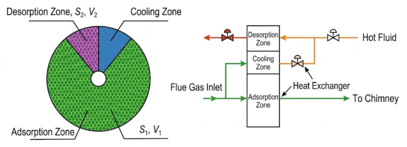
The zeolite molecular sieve rotary concentrator (model BL-ZN-400) is the core enabling technology in this system. It uses the continuous adsorption-desorption-cooling cycle of a large rotating disc impregnated with hydrophobic zeolite channels to achieve a 20:1 volumetric concentration of the VOC stream.
The rotor operates across three functional zones simultaneously as it rotates: (1) Adsorption zone (large sector, area S₁): the full 60,000 m³/h of pre-filtered exhaust air passes through the hydrophobic zeolite channels; VOC molecules adsorb selectively onto the zeolite surface; clean air exits and is discharged; (2) Desorption zone (small sector, area S₂, approximately 1/20 of the rotor area): a small stream of hot air at 180–200°C (approximately 3,000 m³/h, heated by the plate heat exchanger using CO outlet hot gas) passes through the zeolite channels in the reverse direction, stripping the adsorbed VOCs; the desorption outlet is a small-volume, high-concentration VOC stream at approximately 3,000 mg/Nm³ — the CO system inlet; (3) Cooling zone (small sector): ambient air cools the just-regenerated zeolite section before it returns to the adsorption zone, maintaining adsorption capacity.
The concentration factor n = (S₁×V₁)/(S₂×V₂) = 20:1. With S₂/S₁ approximately 10:1 and face velocities V₂/V₁ approximately 2, the overall concentration ratio is 20:1. At steady state with 150 mg/Nm³ inlet, the desorption outlet achieves approximately 3,000 mg/Nm³ NMHC.
Zeolite Rotor Advantages and Limitations (as documented)
Advantages
- Concentration ratio up to 25:1 (this project: 20:1)
- Long service life; no scheduled media replacement
- Fully automated DCS control; unattended operation
- Safety certified; meets explosion-proof requirements
- Adsorbs aromatic solvents effectively; excellent benzene-series performance
- Rotor adsorption output concentration is stable and continuous
Limitations
- Pre-treatment required (remove dust and oil mist)
- Requires pre-processing to remove paint aerosol
Zeolite Rotor Specification
| Parameter | Specification |
|---|---|
| Model | BL-ZN-400 |
| Processing flow | 60,000 m³/h |
| Concentration ratio | 20:1 |
| VOC processing efficiency | >95% |
| Desorption temperature | 180–200°C (heated by plate HX using CO outlet hot gas) |
| Dry filter stages | G4 / F5 / F9 (three stages) |
04 — CO Catalytic Combustion System
How Pt/Pd Catalytic Combustion Destroys Concentrated VOCs at 250–300°C With Plate Heat Exchanger Energy Recovery
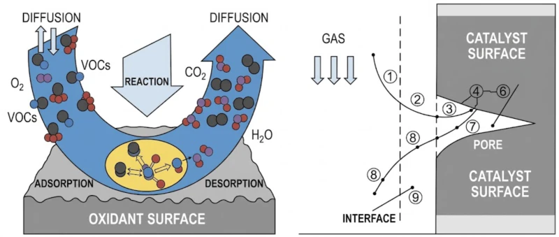
The concentrated 3,000 m³/h desorption outlet (approximately 3,000 mg/Nm³ NMHC) enters the CO (Catalytic Oxidation) system. The CO system uses precious metal Pt/Pd catalysts to oxidise the VOC compounds at 250–300°C:
The Pt/Pd catalyst provides surface active sites where VOC molecules adsorb from the gas phase, react with adsorbed oxygen in a surface chemical reaction, and produce CO₂ and H₂O as the only products. The catalytic mechanism enables this complete oxidation at 250–300°C rather than the 760°C required for thermal (non-catalytic) oxidation. The mechanism is detailed as follows: (1) VOC molecules and O₂ are transported from the gas bulk to the outer catalyst surface; (2) both VOC and O₂ diffuse through the catalyst pore channels; (3) VOC and O₂ are adsorbed on the catalyst surface active sites; (4) the surface chemical reaction occurs at the active site centres, producing CO₂ and H₂O and releasing heat; (5) CO₂ and H₂O desorb from the catalyst surface active centre; (6) CO₂ and H₂O diffuse from the internal catalyst surface to the outer surface; (7) CO₂ and H₂O are transferred from the outer catalyst surface to the gas bulk.
Why natural gas instead of electrical heater: The customer facility already has natural gas pipelines. Using natural gas for catalytic reaction heat startup is more cost-effective and more stable than electrical heating. Natural gas provides a higher-density, more stable heat supply, avoiding the startup temperature fluctuations that can occur with electrical heaters. Additionally, the operating cost per unit heat from natural gas is typically lower than equivalent electrical heat in EU energy markets.
Plate heat exchanger energy recovery: The CO outlet hot gas (at approximately 250–300°C) passes through a plate heat exchanger that transfers this heat to the cold desorption inlet air, raising it from ambient to approximately 180–200°C. This heat recovery loop eliminates the need for additional natural gas or electrical energy to heat the zeolite rotor desorption air, creating an energy self-sufficiency loop between the CO system and the zeolite desorption stage. During normal production, the natural gas flow rate approaches 0 m³/h because the catalytic exothermic heat (combined with the heat exchanger recovery) is sufficient to maintain the catalyst temperature and the desorption air temperature simultaneously.
Three Key Advantages of Catalytic Combustion (CO) over Thermal Oxidation (RTO/TO)
- 1
Lower reaction temperature (250–300°C) dramatically reduces supplementary energy: At 250–300°C, the heat losses from the system to the environment are far lower than at 760°C (RTO). The amount of supplementary heat input needed to compensate for losses scales with the temperature differential above ambient. This makes CO systems intrinsically more energy-efficient than RTO for applications where the VOC concentration provides limited exothermic heat, as in this 3,000 mg/Nm³ concentrated stream. - 2
Small footprint (10×6 m) and fast cold startup (20–30 min) suit the production schedule of a discrete manufacturing facility: Construction machinery manufacturing operates in production shifts rather than continuous process. The CO system’s compact footprint and rapid startup enable it to be started and stopped in alignment with the painting line schedule, without the extended heating times required for RTO ceramic bed warm-up. The 220,000 kcal/h burner and 24 m³/h natural gas connection bring the catalyst to operating temperature in approximately 20–30 minutes, allowing the painting line to start VOC treatment almost immediately after plant startup. - 3
No NO𝑥 secondary pollution: Thermal combustion at ≥760°C generates significant thermal NO𝑥 from nitrogen in the combustion air. Catalytic combustion at 250–300°C is below the thermal NO𝑥 formation temperature threshold, so the final combustion products are solely CO₂ and H₂O without secondary nitrogen oxide formation. This is particularly relevant for EU IED compliance in jurisdictions where NO𝑥 stack emissions contribute to ambient NO₂ limits.
05 — CO Catalytic Oxidation System and Full Specification
System Architecture: Four-Stage Dry Filter + Zeolite Rotor + Plate HX + CO Catalytic Combustion
+Ovens
60,000 m³/h
Dry Filter
Paint removal
BL-ZN-400
20:1 conc.
direct stack
discharge
Hot gas →
Desorption air
250–300°C
Pt/Pd
18 mg VOC
96.4%
Selection Parameters and Installed Capacity
| Item | Specification |
|---|---|
| Total treatment flow (zeolite) | 60,000 m³/h |
| CO processing flow | 3,000 m³/h (concentrated stream) |
| Zeolite model / ratio | BL-ZN-400; 20:1; >95% adsorption efficiency |
| Desorption temperature | 200°C (heated by plate HX) |
| Dry filter stages | G4 / F5 / F9 (three progressive stages) |
| Burner rating | 220,000 kcal/h; natural gas 24 m³/h (P: 0.03–0.06 MPa) |
| Adsorption fan | 55 kW |
| Desorption fan | 5.5 kW |
| Control system | 3 kW |
| Combustion-assist fan | 1.5 kW |
| Total installed power | 65 kW (380 V, 50 Hz) |
| Equipment footprint | 10 m × 6 m (very compact) |
| Annual electricity cost | 159,900 RMB (159,900 RMB; adsorption fan dominant) |
| Annual gas cost (min) | 11,200 RMB (startup only; 0 m³/h normal operation) |
| Annual gas cost (max) | 27,200 RMB (max 1.7 m³/h at 3.5 RMB/m³, max scenario) |
06 — Operational Results
Verified: NMHC Online <20 mg/m³ (Local Limit 60), Grade B Enterprise, 96.4% Removal
After commissioning, online CEMS data consistently shows NMHC below 20 mg/m³, satisfying the local permit requirement of 60 mg/m³ with a large compliance margin. The enterprise has achieved Grade B emission classification. The experience summary confirms the key advantages: the zeolite concentrator reduces the treatment volume from large-volume low-concentration to small-volume high-concentration, significantly reducing the equipment capital cost and treatment difficulty; the catalytic combustion technology lowers the organic compound oxidation temperature, saving operating energy; and the plate heat exchanger uses the CO outlet hot gas to heat the desorption air, achieving energy recovery and reducing the gas consumption needed to heat the desorption air.
.webp)
07 — Implementation Cautions
Critical Engineering Lessons for Zeolite + CO Catalytic Combustion Coating Systems
- ⚠️
Catalyst poisoning from paint coating additives and heavy metals requires careful pre-treatment quality management: Industrial coating paints for construction machinery contain a diverse range of additives: anti-corrosion pigments (zinc phosphate, zinc chromate in some legacy formulations), metallic flake pigments (aluminium, zinc), flow agents, and catalysts in two-component (2K) polyurethane paint systems. Some of these additives can volatilise partially during drying and reach the CO catalyst, causing poisoning. The three-stage dry filter (G4/F5/F9) must be maintained in excellent condition to intercept all particulate-associated contaminants before the zeolite. If any paint formulation change introduces heavy metal pigments or reactive additives (particularly isocyanate vapour from 2K PU paints), an engineering review of the impact on the CO catalyst is required before implementation. - ⚠️
The 20:1 concentration ratio is correctly specified for 150 mg/Nm³ inlet — verify this ratio is still adequate if paint formulation changes reduce VOC concentration further: The 20:1 concentration ratio at 150 mg/Nm³ delivers approximately 3,000 mg/Nm³ at the CO inlet. If the facility transitions to lower-VOC or water-borne paints that reduce the inlet concentration to, say, 80 mg/Nm³, the CO inlet drops to 1,600 mg/Nm³ — still above the autothermal threshold for CO catalytic combustion at 250–300°C. However, if inlet concentration drops to 30 mg/Nm³ (as might occur with water-borne low-VOC paints), the CO inlet at 20:1 would be only 600 mg/Nm³, approaching the minimum for stable catalytic combustion without continuous supplementary gas. Monitor CO inlet concentration continuously and plan for possible increase in the concentration ratio (to 25:1) if paint formulation transitions are planned. - ⚠️
Plate heat exchanger fouling from paint-related compounds must be monitored and addressed proactively: The plate heat exchanger transfers heat from the CO outlet hot gas to the zeolite desorption inlet air. Both gas streams carry residual VOC and paint combustion products. Over time, high-boiling point compounds can condense on the heat exchanger plates and reduce thermal transfer efficiency. When the heat exchanger transfer efficiency degrades, the desorption air temperature falls below 180°C, reducing zeolite desorption completeness and increasing the CO inlet concentration variability. Monitor the desorption air temperature continuously; when it falls below 175°C at normal operating conditions, inspect and clean the heat exchanger plates. - ⚠️
CO catalytic combustion startup procedures must be strictly followed: the catalyst must reach 250°C before concentrated VOC gas is introduced: If concentrated VOC gas (3,000 mg/Nm³) is introduced to the catalyst bed before it has reached the minimum activation temperature of 250°C, the VOC will not oxidise completely. Incompletely oxidised intermediates can deposit on the catalyst surface, causing fouling and activity reduction. The startup sequence must: (1) run the natural gas burner with clean air (no VOC) until the catalyst bed reaches ≥250°C; (2) only then open the concentrated desorption stream to the catalyst. The startup procedure must be documented and followed for every restart, not just the initial commissioning startup.
08 — Engineering Takeaways
Four Lessons from This Zeolite + CO Coating Industry Project
- 1
At 150 mg/Nm³ inlet, the zeolite concentrator is not optional — it is the prerequisite that makes any thermal or catalytic oxidation economically viable. Without concentration, treating 60,000 m³/h at 150 mg/Nm³ with any thermal oxidation technology is uneconomical: the gas volume requires large equipment, and the concentration is far below any autothermal threshold. The 20:1 concentration step reduces the treatment problem from “60,000 m³/h that needs continuous supplementary fuel” to “3,000 m³/h that is near-autothermal.” For any coating facility with inlet NMHC below approximately 500 mg/Nm³, the zeolite concentrator should be the default first system element, not an optional upgrade. - 2
CO catalytic combustion at 250–300°C is the right final oxidation technology when the concentrated gas is at 3,000 mg/Nm³ and the facility is a discrete manufacturer with shift-based production. The CO system’s 20–30 minute startup time, compact footprint (10×6 m), and zero supplementary gas at normal load fit the operational requirements of a construction machinery factory better than an RTO (which needs longer warm-up, larger footprint, and is better suited to continuous process facilities). The technology selection must account for the production schedule, not just the gas composition and concentration. - 3
The plate heat exchanger coupling between CO outlet and zeolite desorption is not a peripheral efficiency measure — it is the energy coupling that enables near-zero-fuel normal operation. Without the plate HX, the zeolite desorption air would need to be heated by the natural gas burner from ambient to 180–200°C continuously. The plate HX transfers this heating duty to the CO outlet hot gas, which provides the heat for free. The result is that the 220,000 kcal/h burner is needed only for startup and at the lowest-VOC-load operating conditions. This thermal coupling converts the CO outlet gas from a waste heat stream to the primary energy supply for the zeolite desorption stage. - 4
Catalyst selection (Pt/Pd precious metal on ceramic carrier) is correct for painting VOC at 250–300°C, and the catalyst formulation must be verified against the specific solvent mix of the painting application. Pt/Pd catalysts have high intrinsic activity for benzene-series hydrocarbons (toluene, xylene), esters, and ketones — exactly the solvents present in this construction machinery painting application. The conversion efficiency vs temperature curves for typical painting solvents confirm >95% destruction at 250°C for toluene and xylene, with methyl benzene requiring slightly higher temperature. Selecting a Mn-based or Fe-based base metal oxide catalyst instead of Pt/Pd would reduce catalyst cost but increase the required operating temperature by approximately 50–80°C, partially eroding the energy advantage of catalytic vs thermal oxidation.
09 — Frequently Asked Questions
Zeolite + CO Catalytic Combustion Coating VOC: Ten Questions Answered
Questions from environmental permit managers, production engineers, and EHS teams at coating, painting, and surface finishing facilities planning zeolite concentrator + catalytic combustion systems under EU IED / Dutch Activities Decree requirements.
Very Low VOC Concentration? Zeolite Concentration Is the Answer.
Explore Zeolite Concentrator + Catalytic Combustion Solutions for Coating Industry VOC
From zeolite molecular sieve concentrators combined with CO catalytic combustion for very low-concentration coating VOC to regenerative thermal oxidizers for higher-concentration applications, our engineering team selects the optimal technology for your specific gas volume, concentration, and operating schedule.


